Form No. 56043161 - Clean Track
®
L24 - 71
The secondary function of the main control board is to detect any system failures and display an error code on the
displayLEDpanel,orstoreitinthemaincontrolboard’srecallmemorymode.Theerrorcode(s)areusedtohelpthe
servicepersondeterminethefaultandtoquicklyguideinrepairingaspecicsystemmalfunction.
Note:SeetheTroubleshooting Guidebelowforfurtherinformation.
Anadditionalspecialfeatureofthemaincontrolboardistochangeprogramsettingsforasetofspecicmachine
functions. See the Main Control Programming Options section in this manual for further information.
Troubleshooting Guide
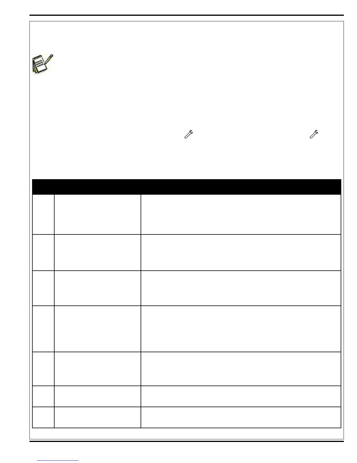
Any error codes detected by main control board will be displayed on the LED display panel as they occur. If more than
oneerrorexists,thedisplaywillsequencethroughtheerrorcodesatone-secondintervals.Theerrordisplaywillshow
on the display LED panel as a mechanical wrench symbol followed by a two-digit code. For example: 03
wouldbeadrivesystemfault.Whentroubleshootingany“FaultDescription”notedwithadoubleasterisk(**)followthe
instructions for entering the Service Test Mode. See the Service Test Mode section in this manual.
Main Controller Error Codes
Display
Code
Fault Description Troubleshooting Action
03 Drive system fault.
1. Check for a tripped drive motor circuit breaker (30 amp). Investigate reason
for possible mechanical overload. Examples: Debris wrapped around the drive
wheels,defectivedifferentialandprolongedrampclimbing.
2. Observethegreenashingwandindicatorlight(onoperatorpanel),thensee
Curtis Controller Diagnostics and Status LED Fault Codes (Table 1) to further
troubleshoot the drive system.
04
Scrub deck lift actuator overload.
• Normal current load - 1 to 2.5
Amps.
• Max. current load 6 Amps.
• Max. current no load - 1.4 Amps.
1. Check for binding or frozen brush lift linkage and excessive weight on brush deck.
2. Checkforshortcircuitsinactuatormotorandwiring.Repairorreplace.*To
test,disconnectthemotorplugandattachtheactuatortestcord(56407502)and
perform an amp draw test. Compare readings to the current loads listed on the
left.
05
Solution pump M1 overload.
• Normal current load .8-1.8 Amps.
• Max. current load 3.2 Amps.
Over will cause 05 pump motor
overload.
1. Check for short circuits in the wiring and pump motor.
2. Disconnect the pump motor and run the machine to see if the wiring is shorted.
3. Check the pump motor to see if it is bad.
06
Scrub motor overload
Note: See Selecting the Scrub
Pressure Current Limits for detail
load current values for the different
scrub pressure limit settings.
1. Check for binding in rotation of brushes or incorrect brush Scrub Pressure lift
actuator operation.
2. Check the negative supply cable at the brush motor for a wiring problem or
incorrectmodications.
3. Check for an open in the small WHT/GRA current sense wire.
4. Checkforshortcircuit*inbrushmotororwiring.
5. Inspect scrub brush drive bearings and drive belts for excessive wear.
07
Vacuum motor overload. Normal
current load 24V 23-25 Amps for
each vacuum motor.
1. Check for debris in the vacuum motors.
2. Worn carbon brushes.
3. Defective motor bearings.
4. Checkforshortcircuit*invacuummotorsorwiring.Repairorreplace.
5. Check for an open in the small ORG current sense wire.
08 Solution solenoid coil L1 overload.
1. Check for wiring problems (short) on the coil circuit and repair wiring.
2. Check the coil resistance. The nominal resistance is 53 ohms for White Rogers
and100ohmsforAmetek.Ifresistanceisbelow45Ohms,replacethesolenoid.
09 Solution solenoid coil L2 overload.
1. Check for wiring problems (short) on the coil circuit and repair wiring.
2. Check the coil resistance. The nominal resistance is 53 ohms for White Rogers
and100ohmsforAmetek.Ifresistanceisbelow45Ohms,replacethesolenoid.
 Loading...