64 - Form No. 56043161 - Clean Track
®
L24
Adjusting the Drive Nut on the Scrub Brush Lift Actuator
1. See Figures 28 and 29. On a new
scrubliftactuatormotor,remove
(spin-off) the Drive Nut (B) and slide
on the Spring Housing Guide (A).
2. Install the short compression Spring
(C) onto the actuator (lead screw)
shaft.
3. Reinstall the plastic Drive Nut (B) as
shown (with the nut pin pocket away
from the motor).
4. Assemble the remaining parts (long
compressionspring,SpringHousing
(D) and mounting hardware).
5. Hold onto the spring housing
assembly and press the rocker
switch to run the drive motor and
retract the spring housing toward the
motor housing (the IN limit).
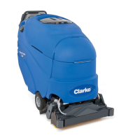
6. Measure the position of the spring
housing assembly on the actuator
shaft. Manually turn the Spring
Housing Assembly to the appropriate
IN position as shown in the chart on
the preceding page.
7. Holdthespringhousingassembly,thenpresstheadaptercordrockerswitchtorunthedrivemotortotheOUT
position (wait until the motor stops).
8. Measure the position of the spring housing assembly on the shaft and compare the measurement with the OUT
position shown in the chart.
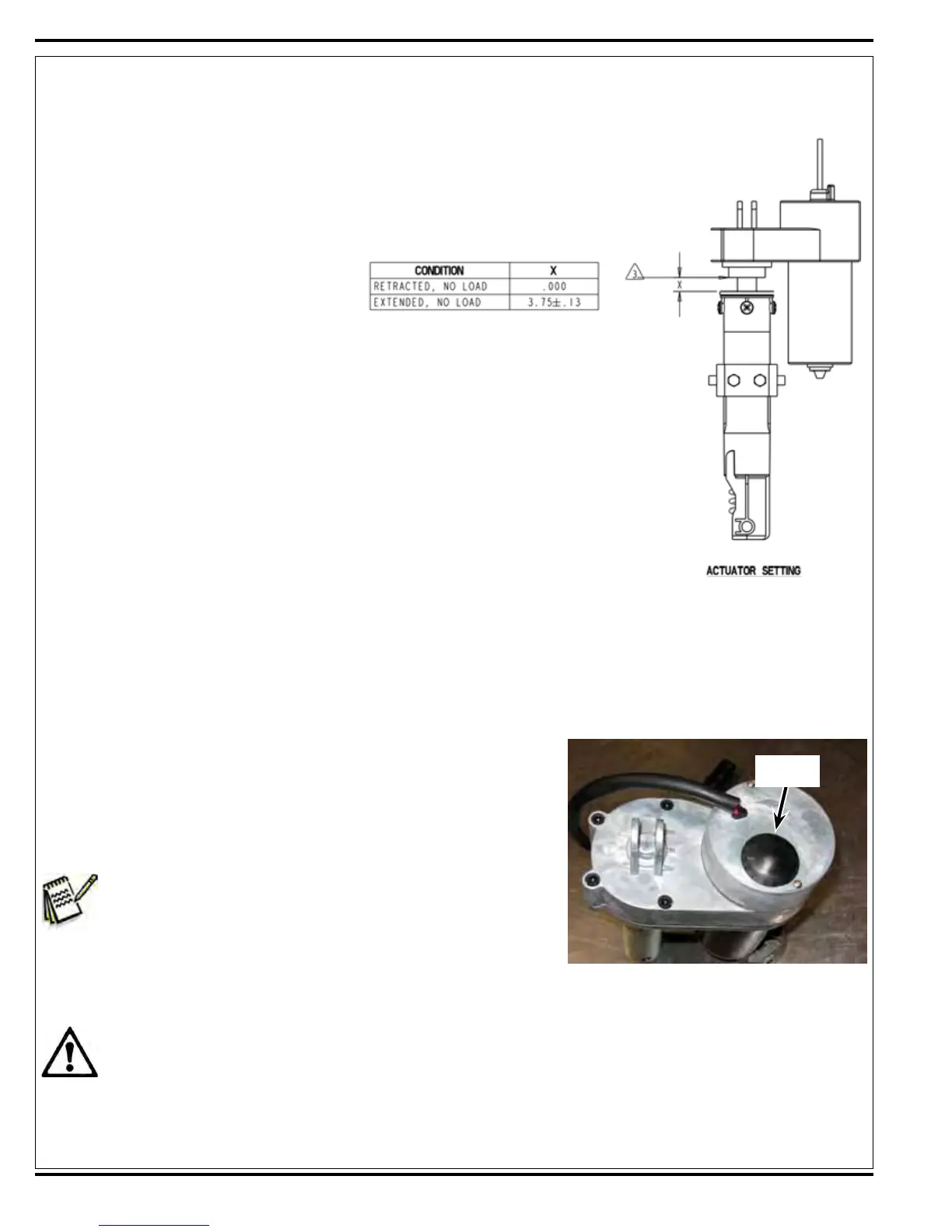
9. Ifthemeasurementdoesn’tmatchthedimensionshowninthechart,
removetheAdjusterCoverandadjusttheOUTposition.
10. Toincreasethetravelofthespringhousingassembly,turnthe
adjusterclockwise.Todecreasethetraveloftheassembly,turnthe
adjustercounterclockwise.
Note:Usea1/2”(13mm)sockettoturntheadjuster.Eachclick
oftheadjusterwillchangethespringhousingassembly
travel1/16inch(1.6mm).
11. Aftereachadjustment,holdthespringhousingassembly,runthe
actuatorINandOUTandcheckbothdimensions.Aftercheckingthatthespringhousinglimitsaresetcorrectly,
replacetheAdjusterCover.
Service Tip:Usetheabovepowercordadaptertohelppositionthespringhousingassembly(inorout)for
easeinactuatormotorinstallations.
12. Afteradjustingtheactuatorspringhousingdimensions,followtheScrub Brush Lift Actuator Removal section to
reassemble.
Figure 28
Adjuster
Cover
 Loading...