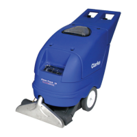
Form No. 56043161 - Clean Track
®
L24 - v
Service Test Mode ............................................................................................ 73
To Enter the Service Test Mode ....................................................................73
Panel Indicators – Service Test Mode ........................................................... 73
To Run the Wheel Drive Motor ......................................................................74
To Switch the Solution System On and Off ...................................................74
To Lower and Raise the Scrub Deck ............................................................. 74
To Switch the Vacuum Motors On and Off ....................................................75
To Extend and Retract the Vacuum Shoe Pin ............................................... 75
To Switch the Scrub Brush Motors On and Off .............................................75
To Switch the On-board Chemical Mixing System On and Off ......................76
Main Control Programming Options .................................................................76
Selecting the Low Voltage Cutout Threshold ................................................76
Selecting the Scrub Pressure Current Limits ................................................76
Restoring the Scrub Pressure Limits to the Factory Default Settings ...........78
Recall Of Stored Error Codes .......................................................................78
Turning Fault Detection On or Off .................................................................78
Displaying the Control Unit Revision Level ...................................................79
Enabling/Disabling the Chemical Mixing System .......................................... 79
Detergent Dilution Ratio Selection ................................................................80
Factory Reset ................................................................................................ 80
Electrical Wiring Diagram/Schematic...................................................................82
Electrical Ladder Diagram ...................................................................................83
Detergent (Chemical Mixing) System Plumbing Schematic ................................84
Detergent (Chemical Mixing) System Preparation and Use ................................85
Note: All references to right, left, front, or rear in this manual are as seen from the
operator’s standpoint.
 Loading...