9 750-265
* All sensors attached to the CB Falcon MUST be all 12K or 10K
sensors (don't mix and match).
The safety mechanism of the Falcon detects drift of the
sensor connected to the NTC1 input if:
• the drift is considerable
• this drift is towards lower measured temperatures
• the actual temperature is large
Actual figures depend on the amount of drift and the actual
temperature.
INSTALLATION
WARNING
Fire or Explosion Hazard.
Can cause property damage, severe injury,
or death.
To prevent possible hazardous boiler operation, verify
safety requirements each time a control is installed on
a boiler.
WARNING
Electrical Shock Hazard.
Can cause severe injury, death or property
damage.
Disconnect the power supply before beginning
installation to prevent electrical shock and equipment
damage. More than one power supply disconnect can
be involved.
When Installing This Product…
1. Read these instructions carefully. Failure to follow them
could damage the product or cause a hazardous condi-
tion.
2. Refer to the wiring diagram provided as part of the appli-
ance or refer to Fig. 3.
3. Check the ratings given in the instructions and on the
product to make sure that the product is suitable for
your application.
4. Installer must be a trained, experienced combustion
service technician.
5. Disconnect the power supply before beginning installa-
tion to prevent electrical shock and equipment damage.
More than one disconnect may be involved.
6. All wiring must comply with applicable local electrical
codes, ordinances and regulations.
7. After installation is complete, check out product opera-
tion as provided in these instructions.
Vibration
Do not install the relay module where it could be subjected to
vibration in excess of 0.5G continuous maximum vibration.
Weather
The relay module is not designed to be weather-tight. When
installed outdoors, protect the relay module using an
approved weather-tight enclosure.
Mounting The CB Falcon
1. Select a location on a wall, burner or electrical panel.
The Falcon can be mounted directly in the control cabi-
net. Be sure to allow adequate clearance for servicing.
2. Use the Falcon as a template to mark the four screw
locations. Drill the pilot holes.
3. Securely mount the Falcon using four no. 6 screws.
NOTE: The device can be removed and replaced in the field
without rewiring.
WIRING
WARNING
Electrical Shock Hazard.
Can cause serious injury, death or property
damage.
Disconnect power supply before beginning wiring to
prevent electrical shock and equipment damage. More
than one disconnect may be involved.
Ground Connection
The ground connection on the controller must not be used as
a central ground connection for the 120 Vac connections.
1. Use the common ground terminal next to the controller,
close to connector J4-12.
2. Connect the central ground terminal with the connection
contact of the controller.
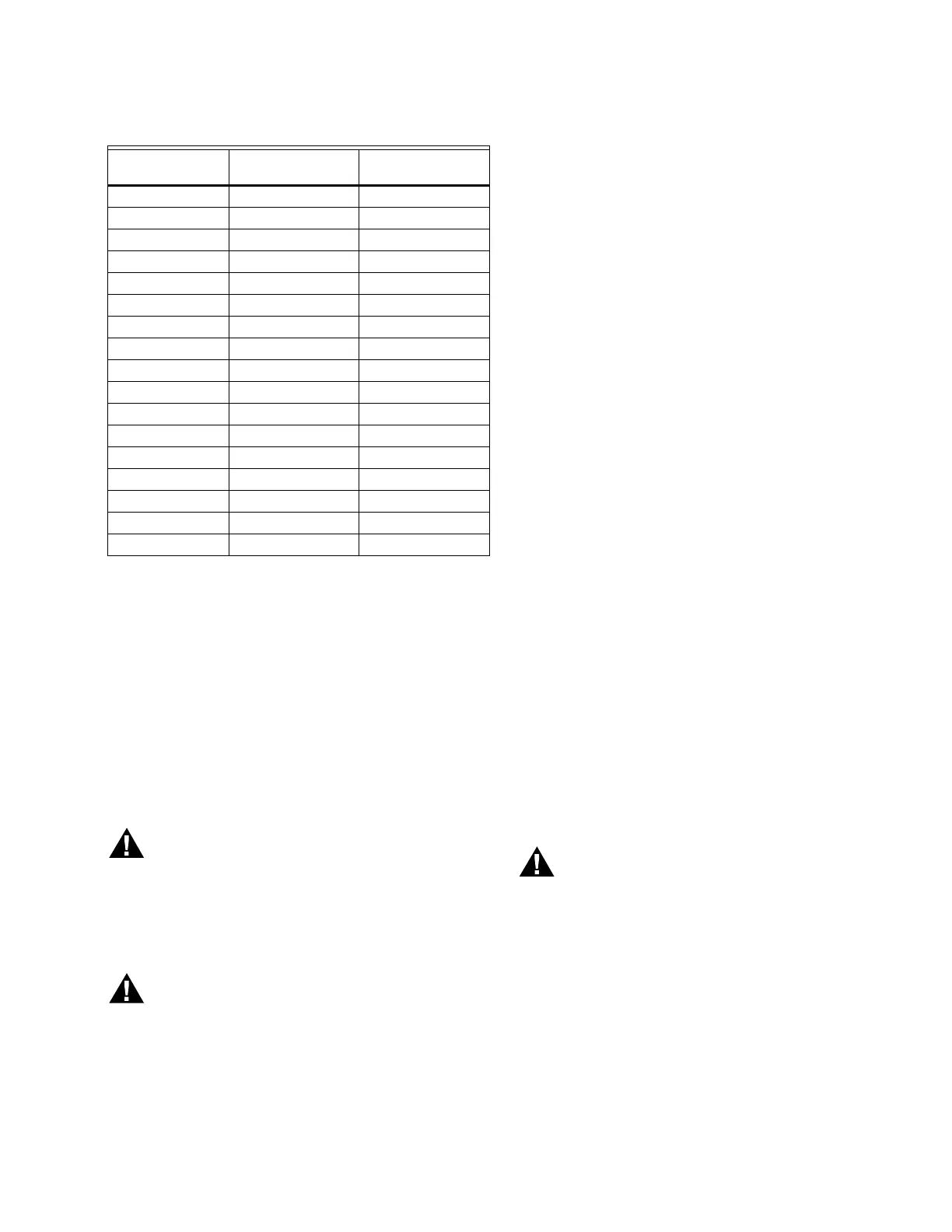
Table 1. NTC Sensors (temperature vs. resistance)
Temp C (F)
12K NTC (kOhm)*
Beta of 3750
10K NTC (kOhm)*
Beta of 3750
-30 (-22) 171.70 176.08
-20 (-4) 98.82 96.81
-10 (14) 58.82 55.25
0 (32) 36.10 32.64
10 (50) 22.79 19.90
20 (68) 14.77 12.49
25 (77) 12.00 10.00
30 (86) 9.81 8.06
40 (104) 6.65 5.32
50 (122) 4.61 3.60
60 (140) 3.25 2.49
70 (158) 2.34 1.75
80 (176) 1.71 1.26
90 (194) 1.27 0.92
100 (212) 0.95 0.68
110 (230) 0.73 0.51
120 (248) 0.56 0.39