Section 2 — Installation
2-6 Part No. 750-263
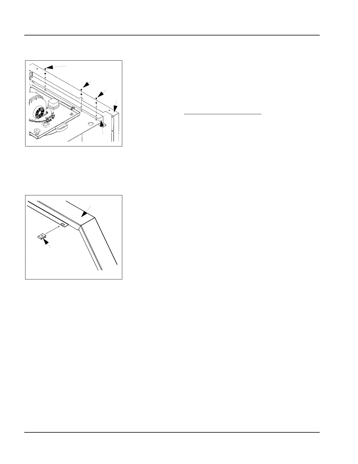
5. Casing Assembly
1. After removing the nuts and washers, attach the electrical
supplychannels (2), left and right, on the mounting studs projectingfrom
the top plate of the boiler (see Figure 2-4). Do not installnuts and
washers.
2. Attach the side panels (3) and (5) on top of the electrical supplychannels.
Fasten loosely with the provided nuts (2a) andwashers (3a).
Casing panels that are mounted with snap-in or “keyhole” type
connections do not need tools
(See Figure 2-6 for next steps).
3. Remove the control panel (7) from the box and mount at thefront. The
control panel is suspended by the side casing panels.
4. Route and connect electrical harnesses and cabling per Figure 3-17.
Include:
• Sensor wiring/cables
•Ignition cables
•Blower cables
• Flame rod cable
5. Run main power to mounting block and fasten wires.
6. Attach the provided c-clips (9, Figure 2-5) to the sidewalls (9a& 9b) and
slide on to bottom side panels.
7. Attach the front cover (10) with self-tapping screws (see Figure2-6).
8. Attach rear walls (11, 11a, 11b) to the side panels.
9. Attach top panel (12).
Figure 2-4 Attaching electrivcal
supply channels and side panels
Figure 2-5 C-Clip retaining nuts