833-3577 CB-FALCON SYSTEM OPERATOR INTERFACE
750-241 3 65-0296—01
SAFETY FEATURES
The 833-3577 contains software that incorporates many
features that are designed to guide you safely through the
commissioning process. Safety, however, is your
responsibility.
Read all documentation carefully and respond appropriately to
all error messages.
WARNING
Explosion Hazard.
Improper configuration can cause fuel buildup and
explosion.
Improper user operation may result in PROPERTY
LOSS, PHYSICAL INJURY or DEATH.
The 833-3577 System Display used to change
parameters, must be attempted by only experienced
and/or licensed burner/boiler operators and
mechanics.
INSTALLATION INSTRUCTIONS
Mounting the 833-3577 and Power Supply
The 833-3577 can be mounted on the door panel of an
electrical enclosure.
1. Select the location on the door panel to mount the unit;
note that the device will extend into the enclosure at
least one inch past the mounting surface.
2. Provide an opening in the panel door 8-1/8 in. wide by
5-7/8 in. high.
3. Place the 833-3577 in the opening and use it as a tem-
plate to mark the location of the four mounting screw
holes. Remove the device.
4. Using the pilot holes as guides, drill 1/4 in. holes
through the door panel.
5. Place the 833-3577 in the opening, aligning the mount-
ing holes in the device with the drilled holes in the panel.
6. Secure the 833-3577 to the panel with four #6-32
screws and nuts provided.
7. Select a location inside the enclosure for mounting the
power supply.
8. Using the power supply as a template, mark the loca-
tions of two mounting holes in the enclosure.
9. Remove the power supply.
10. Drill 1/4 in. holes through the panel at the marked loca-
tions and secure the power supply with the two #6-32
screws and nuts provided.
11. Remove the 9-pin connector plug from the back of the
833-3577.
12. Wire the connector to the power supply and the RS-485
cables using the wiring diagram in Fig. 2.
13. Ensure the 9-pin connector plug is aligned with the
header pin when inserting the 9-pin connector plug back
onto the 833-3577. Secure firmly.
WIRING
The 833-3577 must be appropriately wired for both power and
communications. An external 12V power supply (provided)
with an appropriate power rating is connected to pins 1 and 2
to power the device.
Communication is done over two RS-485 busses:
• COM1 connected directly to the 833-3639 Modbus (MB1)
or Modbus (MB2).
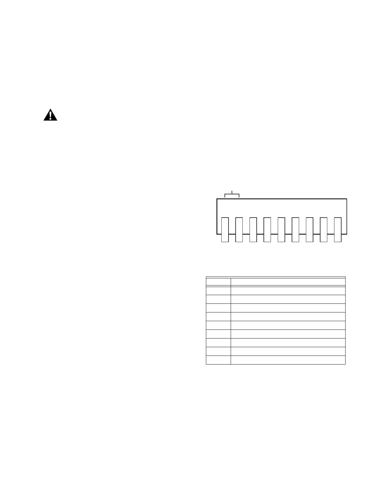
See Fig. 2 for connector terminals. 833-3577 wiring
connections are listed in Table 1. See Fig. 3 for wiring.
Fig. 2. 833-3577 connector terminals.
An RJ45 jack can optionally be wired with a 10 base-T
Ethernet cable for Internet access.
Table 1. 9-pin Connector Terminals
Pin # Function
1 12V input
2 12V input
3 Common (Power, COM 1)
4 COM 1 (b) to Global or Local Modbus™
5 COM 1 (a) to Global or Local Modbus™
6 Not used
7 Not used
8 Not used
9 Not used
1 2 3 4 5 6 7 8 9
M28164
COMMON (c)
COM1 (b)
COM1 (a)
N/C
N/C
N/C
N/C
+12V