Chapter 4 — CFC Commissioning
4-2 Part No. 750-263
A.OPERATING CONDITIONS
• The installation site should be as free as possible from vibration,
dust, and corrosive media
• The controllers should be located as far as possible from sources
of electromagnetic fields, such as frequency converters or high-
voltage ignition transformers
• Control panel must be connected to earth ground.
B.FILLING BOILER
Open the vent valve and fill the boiler slowly to allow entrapped air
to escape. Do not close the vent valve until water emerges. Check
to ensure that no leaks appear at any pipe connections and correct
if water leaks are noticed.
C.CONTROL SETPOINTS
Preliminary settings of the burner/boiler safety controls are
necessary for the initial starting of the boiler. After the burner has
been properly set, minor adjustments to these controls may be
necessary for the particular installation. For initial starting, set the
following controls accordingly:
1. Combustion Air Proving Switch - Set the dial @ minimum.
2. Low Gas Pressure Switch - Set the dial @ minimum.
3. High Gas Pressure Switch - Set the dial @ maximum.
4. High Air Pressure Switch - Set the dial @ maximum.
Depress all manual reset buttons for all controls prior to starting.
D.MODEL CFC BOILER / BURNER CONTROLLER
The Model CFC boiler uses the CB Falcon hydronic boiler control
system. Primary controller functions include:
• Flame supervision
• Heating/modulation control
• Hot water system pump control
• High Limit temperature control
Additional features include:
• User-friendly touchscreen interface
• Modbus communication capability
• Alarm/lockout messaging with history (last 15 messages)
Boiler room ambient conditions
Relative humidity < 85% non-condensing
Ambient temperature range 0
o
C to 50
o
C / 32
o
F to 122
o
F
Storage temperature range -40
o
C to 60
o
C / -40
o
F to 140
o
F
Figure 4-1 Opening Control
Panel
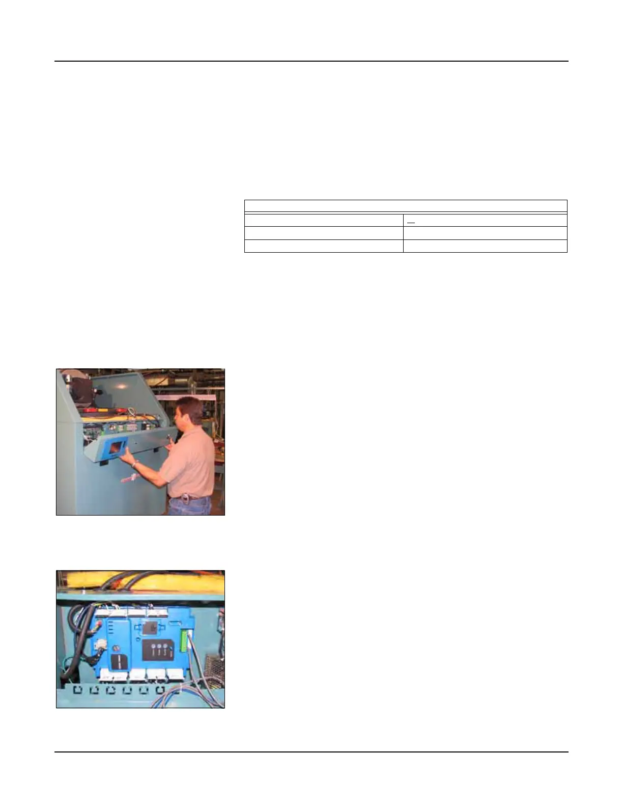
Figure 4-2 CB Falcon Controller