Section 2 — Installation
Part No. 750-263 2-11
The inlet supply pressure must be as noted in Table A when firing
the boiler at low fire and high fire. Actual gas pressure should be
measured when the burner is firing using a manometer at the
upstream test port connection on the main gas valve. For a multiple
unit installation, gas pressure should be set for a single unit first,
then the remaining units should be staged on to ensure that gas
pressure drop is not more than 1" w.c. and never below the required
pressure. Fluctuating gas pressure readings could be indicative of
a faulty supply regulator or improper gas train size to the boiler.
4. Gas Piping
CFC units are not standardly equipped with an upstream gas
pressure regulator. Therefore, a regulator must be installed at each
CFC unit. Do not use a common regulator to regulate pressure for a
multiple unit installation. Note: Gas connection is at the rear of the
boiler, left hand side as you face the rear of the boiler.
If local code permits, a flexible connection can be used between the
gas line and gas valve. This will enable the burner door to be opened
without disconnecting the gas line.
The regulator for each boiler must be installed with at least 2 feet of
pipe between the regulator and the boiler gas train connection. The
discharge range of the regulator must be able to maintain gas
pressures as noted in Table A.
For buildings or boiler rooms with gas supply pressure exceeding 28"
w.c. a "full lock-up" type regulator is required as well as overpressure
protection (e.g. relief valve).
In addition to the regulator, a plug type or "butterball” type gas
shutoff cock should be installed upstream of the regulator for use as
a service valve. This is also required to provide positive shutoff and
isolate the unit during gas piping tests.
If necessary a strainer should be installed upstream of the regulator
to remove debris from the gas supply.
Drip legs are required on any vertical piping at the gas supply to
each boiler so that any dirt, weld slag, or debris can deposit in the
drip leg rather than into the boiler gas train. The bottom of the drip
leg should removable without disassembling any gas piping. The
connected piping to the boiler should be supported from pipe
Table 2-1: Gas Pressure
Boiler Input
Pressure Required at gas
train connection
Maximum
allowable
pressure
Low Fire High Fire
500 - 1000 7" w.c. 5" w.c.
14” w.c.
1500 10" w.c. 7" w.c.
1800 7" w.c. 5" w.c.
2500 9.5" w.c. 7" w.c.
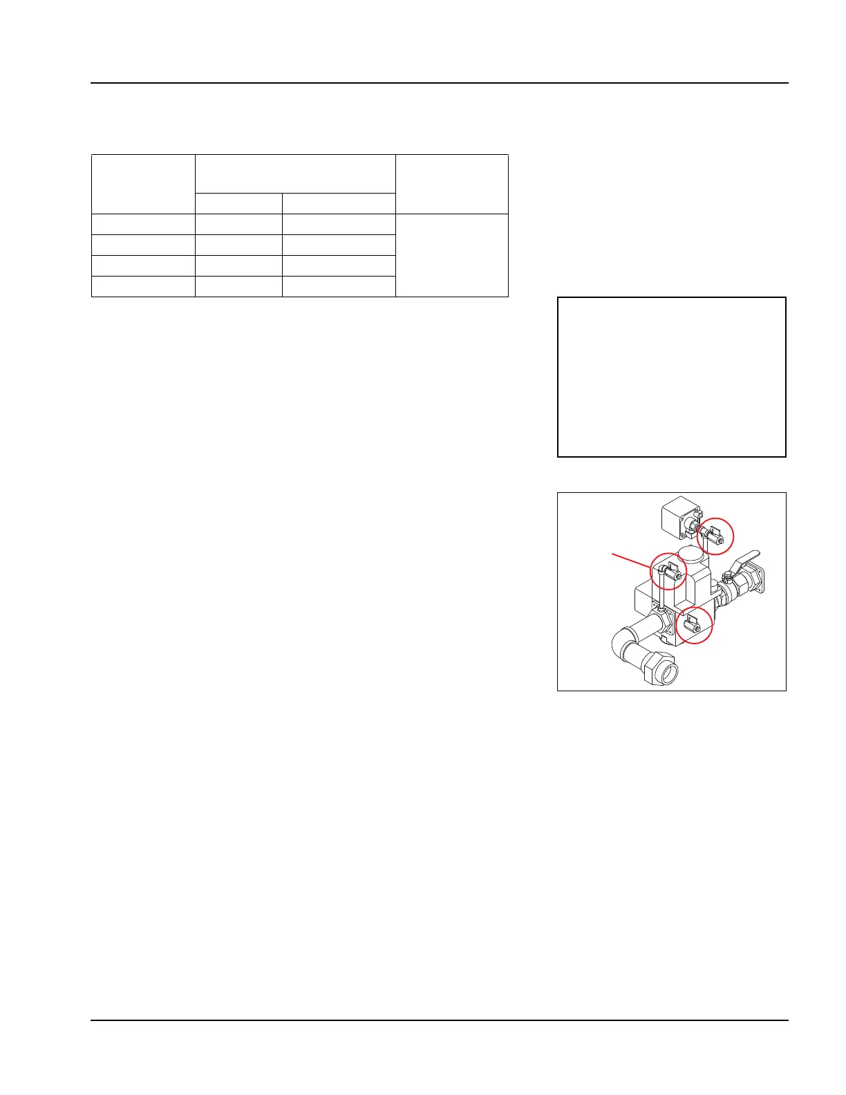
NOTE: The pressure test port is
located at the gas valve inlet
flange (see Figure 2-11). The
remaining try-cocks are for leak
test purposes and should not be
used to measure gas pressure.
Refer to
APPENDIX C - GAS VALVE
INSTALLATION AND MAINTENANCE
for more information.
Figure 2-11 Test cocks - gas
valve