Chapter 4 — CFC Commissioning
4-14 Part No. 750-263
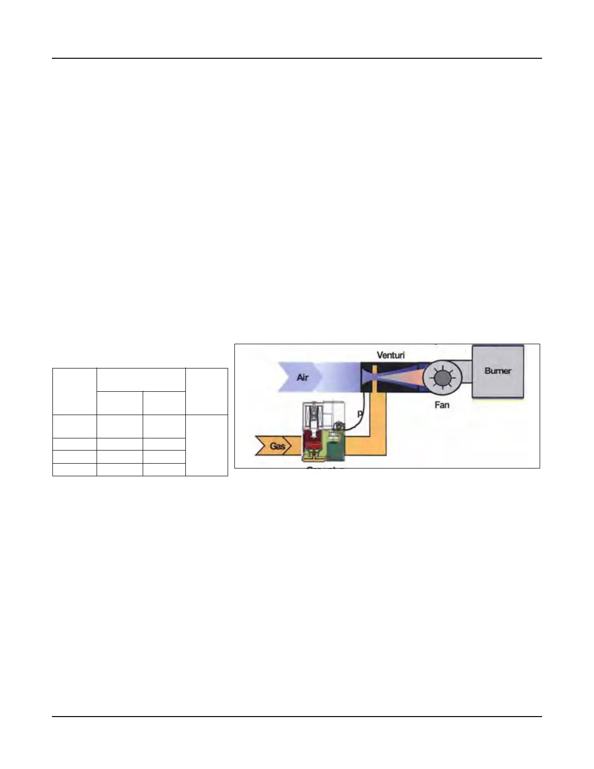
about a change in the gas flow proportional to the air pressure. The
gas follows the airflow in a set ratio, so that fuel always matches
the air as the burner firing rate increases or decreases.
1. Check the gas delivery system to be sure it is properly piped and
wired.
2. Review available gas pressure to assure it is compatible with the
main gas regulators upstream of the Model CFC gas train. Note:
The maximum rated inlet pressure to the CFC gas train is 1/2
psig (14.0" WC). An upstream regulator and overpressure
protection are required if building supply gas pressure is
greater than 1 psig.
3. To bleed air from the supply pipe, open the manual gas shut off
valve upstream of the burner gas train and bleed air from the
piping by loosening the union in the upstream piping.
4. The burner and its gas connection must be leak tested before
placing the boiler into operation.
5. Gas Pressure Regulator - Using the adjusting screw on the main
gas regulator, adjust the inlet pressure to the recommended
levels in Table 4-3.
2. Power-Up
1. Ensure blower motor is properly wired for the available power
supply.
2. Verify the voltage (control voltage is 115V-1Ph.-60Hz) to ensure
it is within specifications.
3. Operation Check: Gas Valve, Gas Pressure Switches,
and Combustion Air Proving Switch
Before initial firing of the burner, the gas valve, Low Gas Pressure
Switch (LGPS), High Gas Pressure Switch (HGPS), and Combustion
Air Proving Switch (CAPS) should be checked for proper operation.
Table 4-3 Model CFC Gas
Pressure Requirements
Boiler
Input
Pressure Required at
gas train connection
Max.
pressure
Low Fire High
Fire
500-
1000
7" w.c. 5" w.c.
14” w.c.
1500 10" w.c. 7" w.c.
1800 7" w.c. 5" w.c.
2500 9.5" w.c. 8" w.c.
Figure 4-8 Premix Burner Technology - Full Modulation