Chapter 4 — CFC Commissioning
4-16 Part No. 750-263
HGPS and GAS VALVE
1. Open the upstream manual shutoff valve and wait a few
moments for gas pressure to rise.
2. Lower the switch setting to minimum.
3. Initiate burner sequence. During the main flame establishing
period, verify gas valve LEDs energize, indicating both safety
shutoff valves open.
4. The CB Falcon should lock out on an interlock failure (Lockout
67).
5. Reset CB Falcon.
6. Open the downstream manual shutoff valve to clear the lockout
condition.
7. Dial the HGPS back to its maximum setting and reset.
IGNITION FAILURE CHECK
7. A test of the flame rod circuit can also be performed at this time.
Disconnect the flame rod cable and attempt to start the burner.
The CB Falcon should lock out, indicating Lockout 109 Ignition
Failure.
8. Replace flame rod electrode and grounding tab.
After verifying proper operation of LGPS, HGPS, CAPS, and Gas
Valve, re-open the downstream manual shut-off valve.
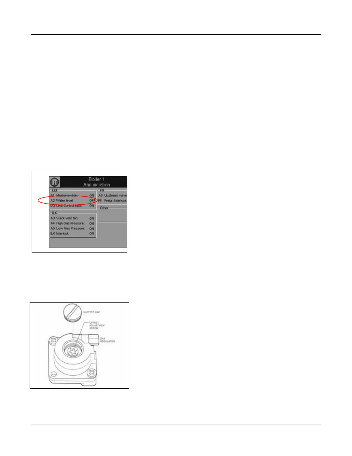
4. LOW WATER CUTOFF Check
1. Hold down the LOW WATER RESET-TEST switch for 3 seconds.
2. Check Annunciation screen. The LCI section (Limit Control Input
circuit) should show A2 Water level: OFF (Figure 4-8).
3. Press RESET-TEST switch once to reset.
5. Low and High Fire Adjustments
All CFC boilers are factory tested firing natural gas at an altitude of
1000 ft ASL. Operating under different conditions may require re-
adjustment of the gas valve.
Adjustments are made using a TORX® T40 (low fire adjustment)
and 3 mm hex wrench (main gas choke). The adjustment screws
should initially be set to half way through each setting’s range. The
low fire adjustment screw is accessed by removing the slotted cap
on the gas regulator using a blade screwdriver (see Figure 4-11).
The high fire adjustment screw is accessed by removing the blue
plastic cap from the valve cover (see Figure 4-12).
Turn the adjustment screw completely clockwise, counting the turns
until the screw will no longer turn. Then, turn the adjustment screw
counterclockwise half the number of turns counted when turning
clockwise.
Figure 4-10 Low Water Cutoff
test
Figure 4-11 Regulating
Adjusting Screw - Low Fire
Offset