Section 2 — Installation
2-28 Part No. 750-263
1. Condensate Tank Setup Options
The boiler is supplied with boiler legs (standard) which are sized to
permit the installation of the condensate collection tank. There are
two (2) condensate tank styles available:
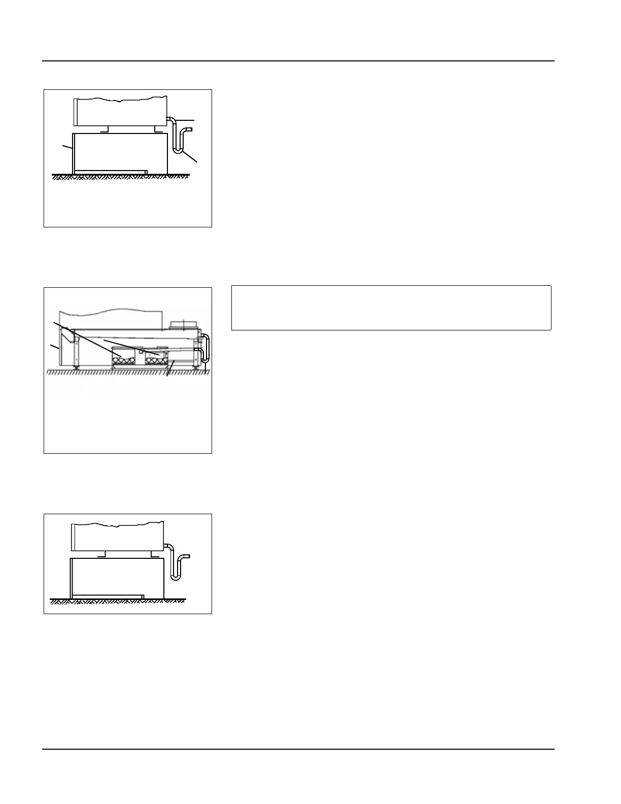
(1) The condensate is piped directly to a drain through the piping
and water trap supplied during installation (see Figure 2-29).
(2) The condensate is held in a condensate tank under the boiler.
The condensate is neutralized as it passed through the granular
bed. The neutralized condensate is then piped to the drain (see
Figure 2-30).
2.
Condensate Take-off and Neutralization
3. Condensate discharge into local drain
For discharge into a local drain a water trap must be installed per
Figure 2-31.
1. Piping is to be a minimum of 3/4” NPT.
2. Maximum discharge pipe height from floor to be 9”.
3. Condensate water trap (6”) required.
4. Piping treated condensate to drain
Figure 2-32 shows the gravity flow condensate treatment assembly.
• Item (1) is the bottom side casing of the boiler.
• Item (2) is the water trap 6” minimum.
• Item (3) is the condensate tank assembly
• Item (4) is the condensate drain line.
• Item (5) is the condensate reservoir tank.
• Item (6) is the piping from trap to the treatment tank.
Figure 2-29 Condensate Piped
Direct to Drain
1
2
3
1. Removable front
2. Min. 6” water trap
Figure 2-30 Condensate Tank
with neutralization material.
1
2
3
4
5
1. Removable Front Panel
2. 6” Water Trap
3. Neutralization Material
4. Plastic Drain Pipe
5. Neutralized Condensate reservoir
To ensure compliance with regulations, it is important to contact the
responsible authorities prior to the planning and execution of the boiler
installation. Condensate flow of 5 to 12 GPH can be expected
depending on boiler size and return water temperature.
Figure 2-31 Condensate
Discharge Piping