Section 2 — Installation
Part No. 750-263 2-3
A.ASSEMBLY
1. Packaging
The Cleaver-Brooks Model CFC boiler is shipped in three parcels.
The pressure vessel assembly mounted on a skidded crate, the
control panel in a box, and the outer casing with insulation in a
skidded box. It is recommended that the pressure vessel be properly
mounted with all piping connections attached prior to installation of
the casing.
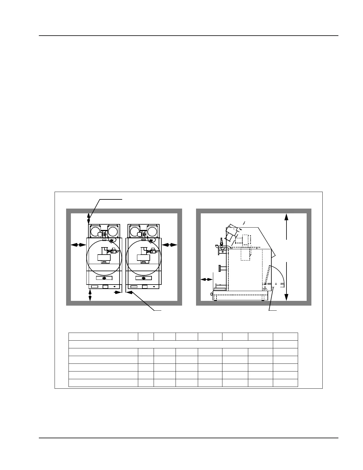
2. Boiler room
The boiler or boilers should be mounted in a space in accordance
with Figure 2-1 shown below. Clearances front, rear, and sides are
provided.
Note: If the boiler room is constructed with non-combustible
walls, it is possible to install the units closer to the side
walls, but the front and rear clearances must be
maintained.
S
Figure 2-1 Clearance Required
Model No. Dim CFC-500 CFC-750 CFC-1000 CFC-1500 CFC-1800 CFC-2500
Space Required (in inches)
Floor to Ceiling A 96 96 96 96 96 96
Side Clearance B 24 24 24 24 24 24
Backway C 24 24 24 24 24 24
Front D 36 36 36 36 36 36
Between Boilers E 3 3 3 3 3 3
B
r
o
o
k
s
C
l
e
a
v
e
r
SIDE VIEW
20"
PLAN VIEW
MULTIPLE BOILERS
Minimum
ceiling height
96 inches
(All Boilers)
Minimum distance from combustible walls - 24 inches.
Minimum distance
between boilers, 3 inches.
24”
24”
24”
36”
24”
B
r
o
o
k
s
C
l
e
a
v
e
r
Fold Down Service
Access Step
A
B
C
D
E