Chapter 3 — Stack and Intake Vent Sizing and Installation
3-10 Part No. 750-263
be taken during assembly to insure that all joints are sealed properly
and are airtight.
For certain installations PVC or CPVC may be used. Contact your
authorized Cleaver-Brooks representative for details.
To prevent the condensation accumulation in the vent, it is required
to install the horizontal portion of vent with a slight upward slope of
not more than 1/4" per foot of horizontal run and an approved
condensate trap must be installed per applicable codes.
No substitutions of flue pipe or vent cap material are allowed.
Such substitutions would jeopardize the safety and health of
inhabitants.
The Stainless Steel non-restricted direct vent cap must be furnished
in accordance with AGA/CSA requirements.
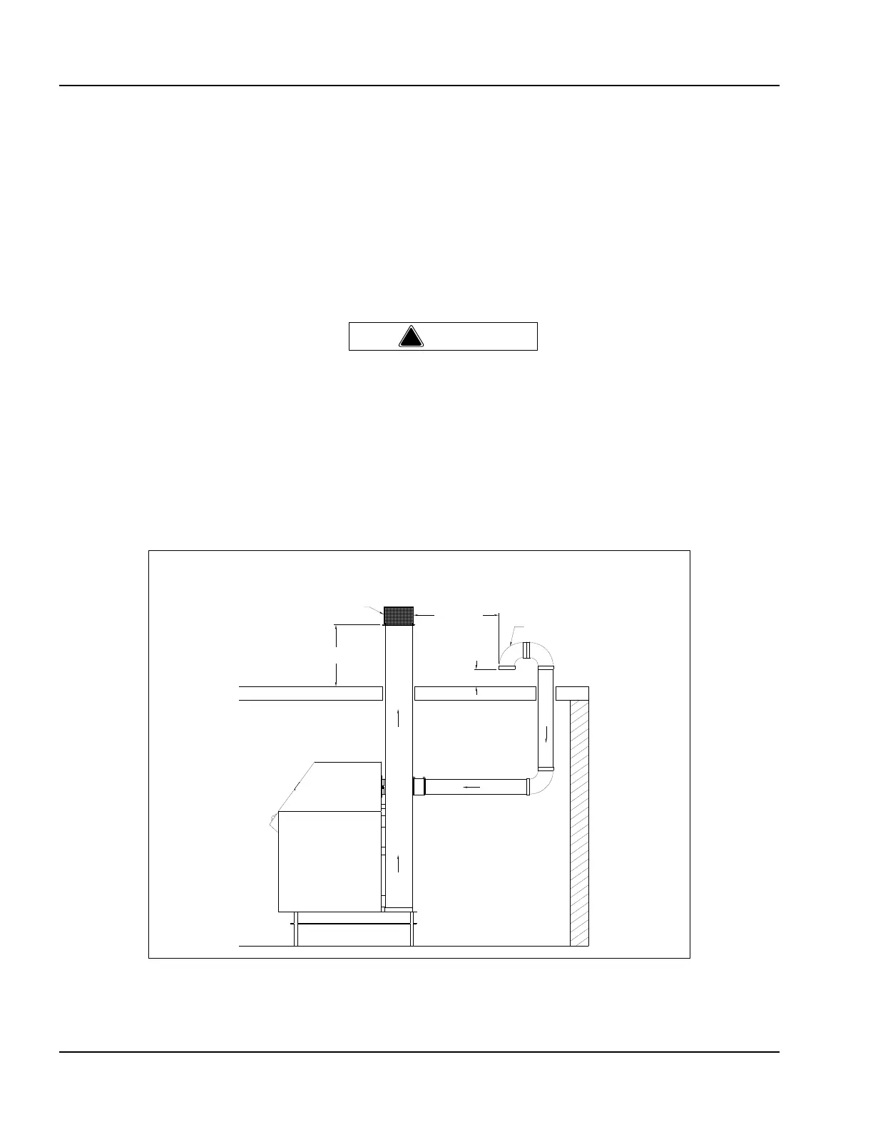
E. VERTICAL VENTING / DIRECT VENT
COMBUSTION AIR
(CATEGORY III & IV)
Figure 3-6 Vertical Stack with Direct Vent Combustion Air
Boiler
Flue Gas Vent (w/Screen)
Air Intake (w/Screen)
36" Minimum
24"
Minimum
12"
Minimum