833-3577 CB-FALCON SYSTEM OPERATOR INTERFACE
65-0296—01 4 750-241
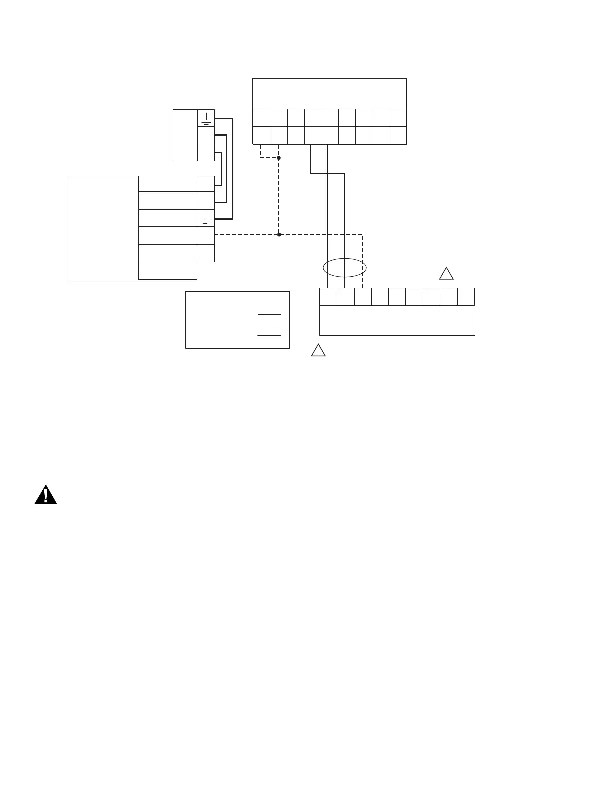
Fig. 3. Wiring diagram.
QUICK SETUP
1. Make sure the 833-3577 9-pin connector is properly
aligned and pressed firmly in place.
2.
Make sure the 9-pin connector is connected securely to
the 833-3639 controller RS-485 communication port.
WARNING
Electrical Shock Hazard.
Can cause severe injury, death or equipment
damage.
Line voltage is present at the 120 Vac power supply.
3. Make sure the +12 Vdc power supply (supplied with the
833-3577) is connected securely to the 120 Vac power
source.
STARTING THE DISPLAY
Power-up Validation
The Home page will appear and the POWER LED will be
blinking when the device is properly powered. Select the
Setup button to adjust the contrast as desired.
If the screen is dim, check pin 1 wiring connections.
NOTE: An Advanced Startup screen displays for five sec-
onds after power-up before the Home page displays.
This screen allows the user to upgrade the software
in the 833-3577 System Display (see “Preface” on
page 2) and should normally be bypassed.
Communication Validation
Three LEDs exist for I/O traffic, one for the Ethernet port and
two for the Modbus™ ports.
1. Make sure the LEDs are blinking.
2. If the LEDs are not blinking:
a. Make sure the proper connections have been made
between the 833-3577 Modbus™ Com 1 Port and
the first 833-3639 device in the Modbus™ global net-
work.
b. See “Wiring” on page 3 for proper wiring of the 833-
3577 9-pin Header Connections.
Home Page
Make sure a screen similar to Fig. 4 appears after the 833-
3577 is completely powered up.
On 833-3577 System applications, each 833-3639 in the
hydronic system is represented on the Home page by an icon
and name. Pressing the icon allows the user to zoom in on
that boiler and see specific details about it. These details are
provided on a new page, which can include additional buttons
that display additional detail and operation information, which
itself leads to other pages. The pages are traversed in a tree
structure method, as shown in Fig. 5.
M28200
21 4 56 78 93
+12
(B) (A)
N/C
GND
(C)
+12
N/C
(A)
(B)
LOCAL DISPLAY
COM1
COM2
L1
L2
120
VAC
V ADJ
V+
N
L
V-
DC OUT
(COMMON GND)
12 DC OUT +
EARTH
GROUND
120VAC (L1)
NEUTRAL (L2)
MEAN WELL S-25-12
DO NOT CONNECT THE LOCAL DISPLAY TO TERMINALS 1 2 3.
THIS WILL RENDER THE DISPLAY INOPERABLE.
POWER SUPPLY
WIRING KEY
LOW VOLTAGE
DATA
LINE VOLTAGE
23CBACBA1
HYDRONIC CONTROL
J3
MB1 ECOMMB2
1
1