Chapter 1 — Introduction
1-4 Part No. 750-263
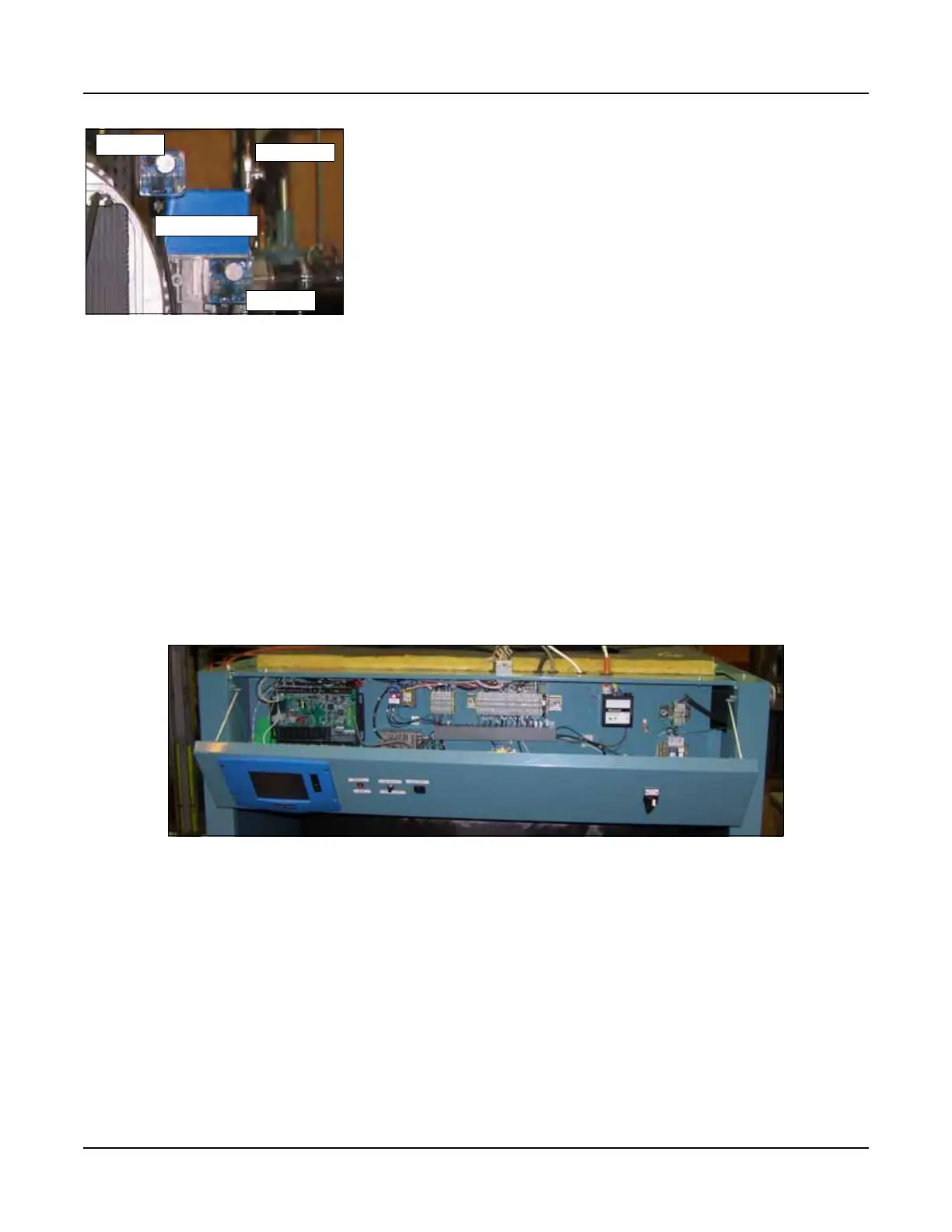
4. Control (See Figure 1-7)
The CB Falcon hydronic control is an integrated burner management
and modulation control with a touch-screen display/operator
interface.
The controller is capable of the following functions:
• Two (2) heating loops with PID load control.
• Burner sequencing with safe start check, pre-purge,
direct spark ignition, and post purge.
• Electronic ignition.
• Flame Supervision.
• Safety shutdown with time-stamped display of lockout
condition.
• Variable speed control of the combustion fan.
• Supervision of low and high gas pressure, air proving,
stack back pressure, high limit, and low water.
• First-out annunciator.
• Real-time data trending.
• (3) pump/auxiliary relay outputs.
• Modbus communication capability.
• Outdoor temperature reset.
5. Component/Connection Locations
Figure 1-8 shows the CFC component orientation and heat flow
path. Note the downfired design of the burner and the orientation of
the hot water outlet and return connections. The return water
connection is at the bottom of the vessel and the hot water outlet is
near the top.
Figure 1-9 shows the locations of the safety valve and low water
cutoff. Figure 1-10 shows the supply and return connections and
the location of the return water temperature sensor. Looking at the
top of the boiler, near the rear, Figure 1-11 shows the three hole
sensor well for the outlet temperature sensor.
Figure 1-6 Standard Gas Train
Components per CSA and ASME
CSD-1
HGPS
LGPS
GAS VALVE
TEST COCK
Figure 1-7 Control panel (hinged access panel open)