Chapter 1 — Introduction
1-8 Part No. 750-263
The stack can be mounted on the right (Figure 1-12) or left (Figure
1-13) side on the back of the boiler base.
The flue gas duct sizes may be reduced at the vent connection.
See also Chapter 4 - Stack and Intake Vent Sizing and Installation.
.
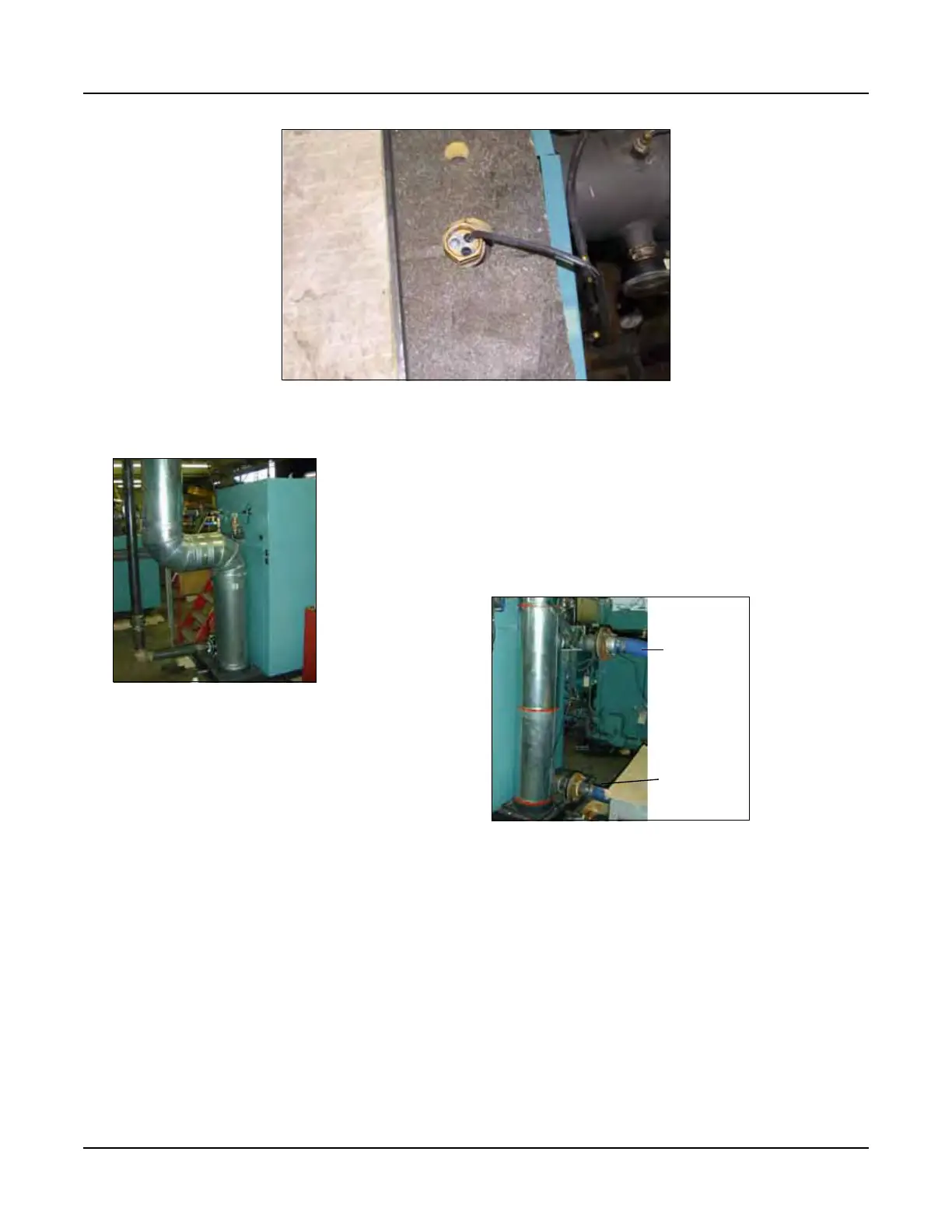
Figure 1-11 Temperature Sensor, Top of Pressure Vessel
Figure 1-12 Stack Right Side
(viewed from rear)
Figure 1-13 Stack Left Side (viewed from rear)
Hot
Water
Out
Return
Water
In