19 750-265
Demand and Rate
The Demand and Rate subsystem produces 2 outputs:
• demand, which tells the burner control it should fire, and
• the modulation rate, which is the burner’s firing rate.
There are three normal sources that share use of the burner:
• Central Heating Demand and Rate (CH DR)
• Domestic Hot Water (DHW DR)
• Lead Lag (LL DR)
These are all similar in that:
• Their inputs are a temperature sensor and a setpoint value.
• Their outputs are:
a. An on/off demand indication that is on if the sub-
system wants the burner to fire.
b. A modulation rate which is a percentage value
between 0% and 100% that the subsystem wants as
the burners firing rate.
• They use a PID calculation to set the modulation rate.
Each of these sources has its own separate parameters.
Additionally there are two sources that can call for burner
firing, but do not use a PID calculation or modulate to a
setpoint: CH Frost Protection and DHW frost protection, which
always fire at the minimum modulation rate.
PID Requirements As a replacement for MCBA
Control:
The internal gain scalers for P, I, and D can be calibrated so
that the gains for a legacy MCBA control can be copied to the
Falcon without conversion at one specific maximum
modulation fan speed. The chosen fan speed for calibrating
these scalers is 5000 RPM, that is, when both the MCBA and
the Falcon have a maximum modulation fan speed of 5000
RPM, the user-programmable P, I, and D gains used by the
MCBA can be directly copied to the corresponding Falcon
parameters, and the behavior of the Falcon control will then
be similar to the MCBA.
At other values of maximum modulation fan speed, the
parameters to provide similar behavior can be calculated as:
GAINICP = GAINMCBA * Max_modulation_fan_speed / 5000
To prevent integral “wind up,” the R7910A’s integrator will be
limited to a maximum value (100%, that is, if I were used
alone without P and D, the output would be 100%) and
integration will be inhibited so that the integrator will not
change its value whenever the proportional term (error times
P gain) alone would provide 100% output (this is typical of a
step-change in setpoint); i.e. values will be added to or
subtracted from the integrator only when the operating point is
within the proportional band.
The CB Falcon will also include a feature to smooth the
response when a rate override has occurred (such as delta-T
rate limit) causing the PID output to be ignored. Whenever an
override has occurred, at the moment the override ends, the
integrator will be preloaded with a value that causes the PID
output to match the current rate, whenever this is possible
within the integrator’s limits.
Demand/Rate Selection and Limiting
These sources of demand and modulation rate are processed
by a priority selector that determines which of the sources
(Central Heating [CH DR], Domestic Hot Water [DHW DR], or
Lead Lag Master [LL DR]) actually has control of the burner.
The frost protection source has control only if none of the
others want the burner to fire.
Additionally, the modulation rate requested by the source can
be overridden by rate limiting, which adjusts the burner firing
rate during abnormal conditions.
The descriptions of the parameters shown in Fig. 4 occur
elsewhere in this document:
• The enables and the DHW priority timeout are in “Burner
Control Operation” on page 52.
• Manual Rate control is in “Modulation Output” on page 40.
• Frost Protection is in “Frost Protection” on page 27.
• Various Rate Limiting inputs are in “Rate Limits and
Override” on page 29.
The Demand/Rate Selection subsystem is connected
internally in the CB Falcon as shown in Fig. 4:
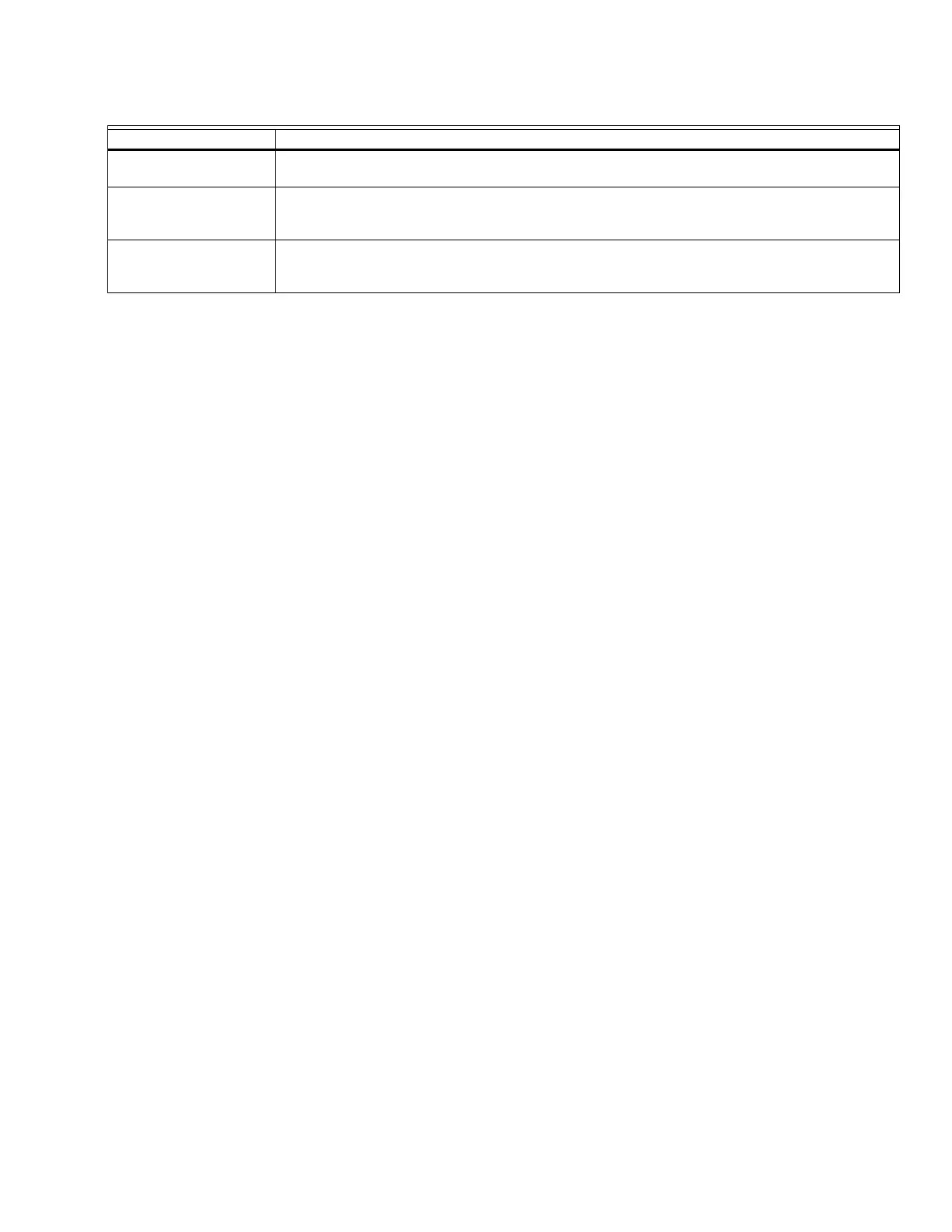
Burner name text
The Burner Name is a text parameter stored in the CB Falcon to identify the burner.
OEM ID text
The OEM ID is a text parameter stored in the Falcon intended for use by an OEM to record
identification information related to the OEM's configuration and setup of the CB Falcon.
Installation Data text
The Installation Data is a text parameter stored in the Falcon. It is intended for use by the installer to
record identification information about how the Falcon was setup at the installation time.
Table 8. General Configuration Settings. (Continued)
Parameter Comment