750-265 22
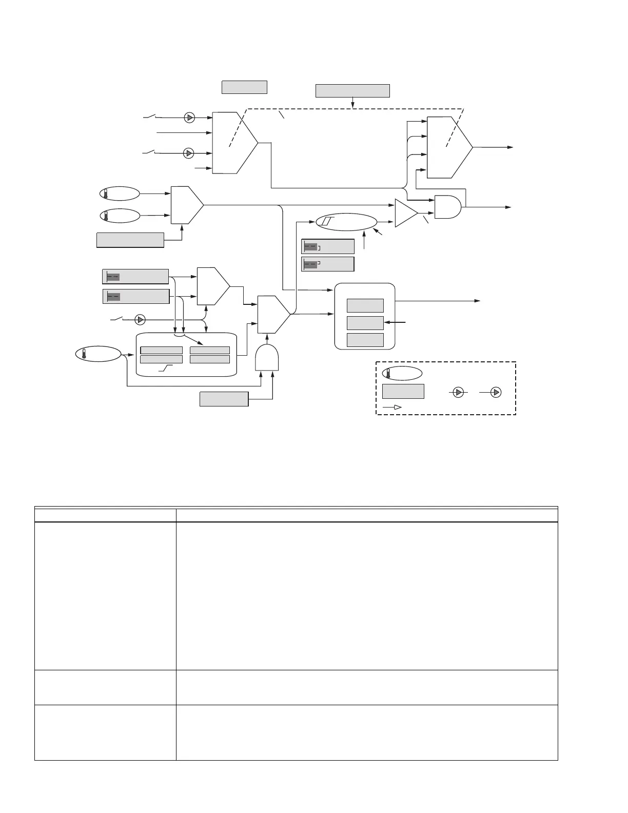
Fig. 7. Central heating diagram.
The function of each parameter and feature is given below.
P-GAIN
I-GAIN
D-GAIN
PID
MIN WATER
MAX OUTDOOR
MIN OUTDOOR
ODR SETPOINT
TOD SETPOINT
SETPOINT
ON HYST.
OFF HYST.
OUTLET
CH BURNER
DEMAND
CH FIRING RATE
HYSTERESIS
TOD
SENSOR IS OK
OUTDOOR
HEADER
STAT
ENVIRACOM REMOTE STAT
(ON/OFF MESSAGE,
WITH TIMEOUT)
CH DEMAND SOURCE
TIME SINCE:
BURNER TURN-ON
BURNER TURN-OFF
BURNER
STATE: ON/OFF
SETTINGS ARE:
TOP: STAT AND SENSOR
REMOTE STAT AND SENSOR
LCI AND SENSOR
SENSOR ONLYBOTTOM:
CH PUMP
DEMAND
1
SETPOINT DEMAND
PARAMETER
SENSOR
“PRATE” = 0 TO 99.99% OF CAPACITY
INPUT
OUTPUT
TERMINALS
CH ENABLE
RESTART
(RESTART INTEGRATOR WHENEVER
A LIMIT OR OVERRIDE ENDS, OR
TURN-ON OCCURS.)
LCI
M24974
CH SENSOR SELECT
ODR ENABLE
Table 9. Central Heating Parameters.
Parameter Comment
CH demand source STAT and Sensor, Remote Stat and Sensor, LCI and Sensor, Sensor Only
The CH demand source may be selected from four options. In all cases, for burner demand
to exist, the sensor must be generating a demand as determined by setpoint and hysteresis
values.
• When “Sensor Only” is chosen, no other input is considered and pump demand is derived
from burner demand.
• When “STAT and Sensor” is chosen, the STAT input in the On condition creates pump
demand and it also must be on for burner demand to exist; if it is off there is no demand.
When “Remote Stat and Sensor” is chosen, a message indicating the remote stat is on
creates pump demand and it also must be on for burner demand to exist; if the message
indicates this stat is off or if no message has been received within the message timeout time
(3–4 minutes), there is no demand. When “LCI and Sensor” is chosen, the LCI input in the On
condition creates pump demand and it also must be on for burner demand to exist; if it is off
there is no demand.
CH sensor Header, Outlet
The sensor used for modulation and demand may be either the Outlet sensor or the Header
sensor.
CH setpoint Degrees or None
This setpoint is used when the time-of-day input is off. If the ODR function is inactive, the
setpoint is used as-is.
If the ODR function is active (input on J10-2), this setpoint provides one coordinate for the
outdoor reset curve, as described in “CH outdoor reset enable” on page 24.