UT-4500 Series C- and Ku-Band Up Converters MN/UT4500.IOM / CD/UT4500.IOM
Table of Contents Revision 3
xv
FIGURES
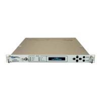
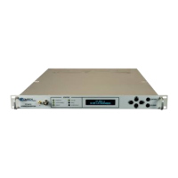
Figure 1-1. UT-4500 Series Up Converters (UT-4505 shown) ............................. 1–1
Figure 1-2. UT-4500 Series Up Converter Physical Configuration....................... 1–2
Figure 1-3. Typical Functional Block Diagram (UT-4512 shown) ........................ 1–4
Figure 1-4. UT-4500 Series Up Converter Dimensional Envelope ...................... 1–7
Figure 1-5. Front Panel View (UT-4505 Shown) .................................................. 1–8
Figure 1-6. Rear Panel (with IOM) – Current Production Unit ......................... 1–10
Figure 1-7. Rear Panel (with TSM) – Initially Released Chassis (OBSOLETE) .... 1–10
Figure 3-1. Unpack and Inspect the Shipment .................................................... 3–1
Figure 3-2. Install the Unit into a Rack Enclosure ............................................... 3–4
Figure 3-3. Install the Optional Rear-Mounting Support Brackets Kit ................ 3–5
Figure 3-4. Install the Optional Rack Slide Set .................................................... 3–7
Figure 4-1. Coaxial Connector Examples ............................................................. 4–2
Figure 4-2. D-Subminiature Connector Examples ............................................... 4–4
Figure 4-3. RJ-45/RJ-48 Connector Example ....................................................... 4–5
Figure 4-4. USB Connector Examples .................................................................. 4–6
Figure 4-5. UT-4500 Series Rear and Front Panels (UT-4505 Current Production
Chassis shown) ............................................................................................. 4–7
Figure 4-6. UT-4500 Series Rear Panel – Initially Released Chassis (OBSOLETE)
(with TSM) ................................................................................................... 4–7
Figure 4-7. Standard AC Power Module .............................................................. 4–8
Figure 4-8. Replace the AC Fuses ........................................................................ 4–8
Figure 4-9. Apply AC Power to the Unit .............................................................. 4–9
Figure 4-10. Optional DC Power Module .......................................................... 4–10
Figure 4-11. Apply DC Power to the Unit .......................................................... 4–11
Figure 4-12. Unit Ground Connection ............................................................... 4–11
Figure 4-13. Rear Panel Operational Connections (with IOM) ......................... 4–12
Figure 4-14. Front Panel Sample Test Point Connections ................................. 4–14
Figure 4-15. UT-4500 Series Cabling Example (with TSM) ................................ 4–15
Figure 4-16. “Personality” Module Examples ................................................... 4–16
Figure 4-17. UT-4500 Standalone Cabling Example to IOM ............................. 4–18
Figure 4-18. UT-4500 Standalone Cabling Example to TSM ............................. 4–18
Figure 4-19. TSM Switching Schematic ............................................................. 4–19
Figure 6-1. Front Panel View (UT-4505 Shown) .................................................. 6–1
Figure 6-2. Rear Panel – Standard and Optional Power Interfaces ..................... 6–2
Figure 7-1. Telnet Interface Example – Windows Command-line ....................... 7–4
Figure 7-2. Telnet Interface Example – HyperTerminal ....................................... 7–5
Figure 7-3. Configure HyperTerminal .................................................................. 7–6