UT-4500 Series C- and Ku-Band Up Converters MN/UT4500.IOM
Front and Rear Panel Connectors Revision 3
4–18
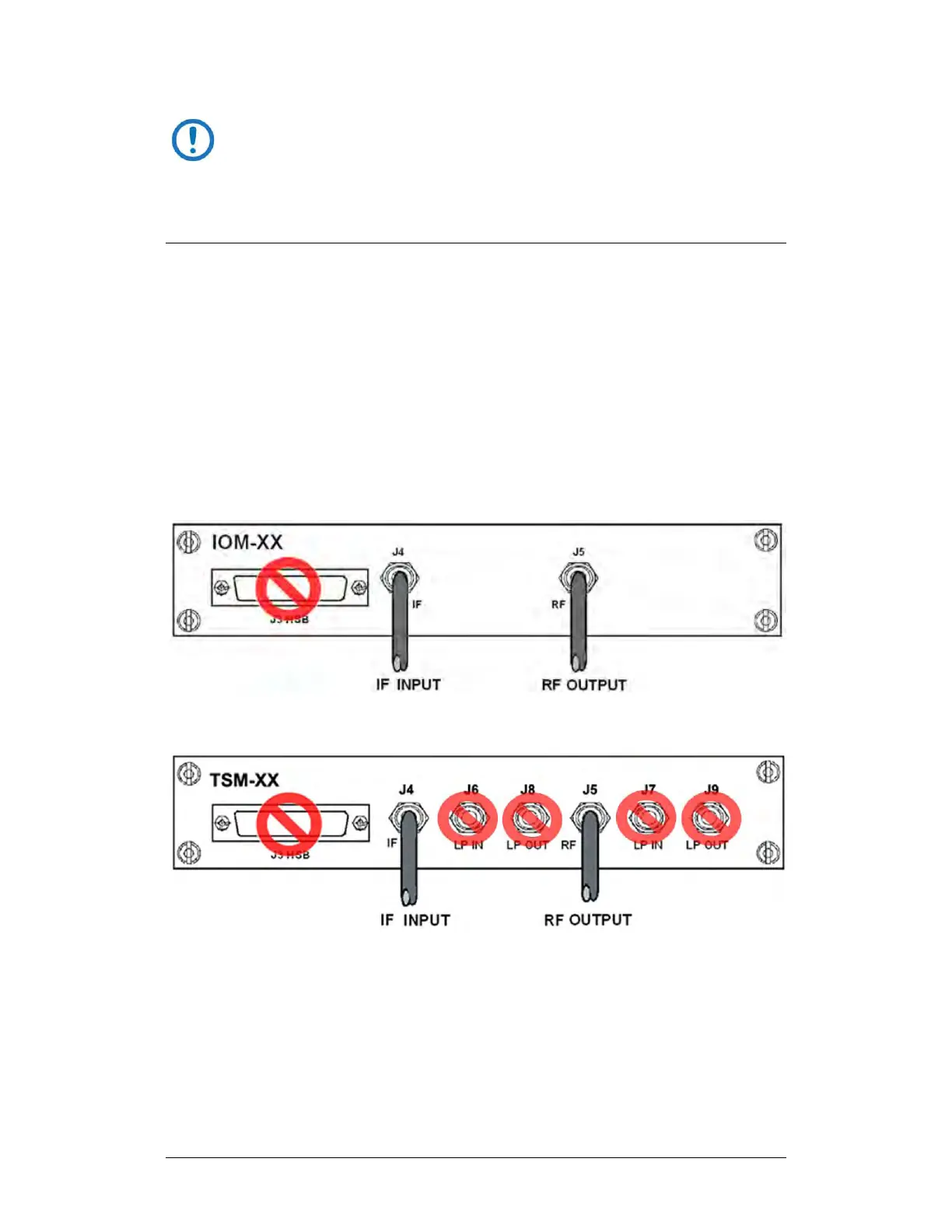
The ‘J3 | HSB’ connector does not employ a “straight-through” cable
assembly. Contact Comtech EF Data Product Support for detailed
cabling instructions when cabling between converters in redundant
applications.
4.2.4.2 Removable Module Operation in Non-Redundant
(Standalone) Applications
A converter may use a Transmit Switch Module (TSM) or a Receive Switch
Module (RSM) in standalone configurations if an IOM (Figure 4-17) is
unavailable.
Note that the High Speed Bus ‘J3 | HSB’ connector is not used in standalone
configurations. If a module other than an IOM is used, only the ‘J4 | IF’ and ‘J5 |
RF' connectors are used to connect directly to the user input/output signal
sources (Figure 4-18).
Figure 4-17. UT-4500 Standalone Cabling Example to IOM
Figure 4-18. UT-4500 Standalone Cabling Example to TSM