UT-4500 Series C- and Ku-Band Up Converters MN/UT4500.IOM
Introduction Revision 3
1–8
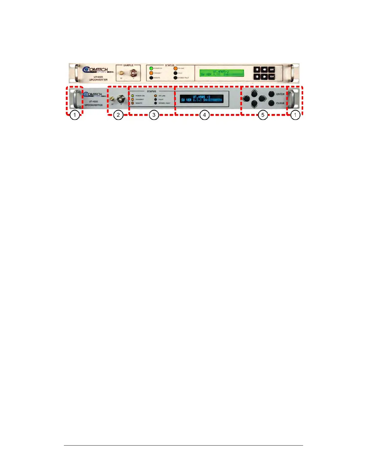
1.3.3 Front Panel
(TOP) Initially Released Chassis
(BOTTOM) Current Production Unit
Figure 1-5. Front Panel View (UT-4505 Shown)
The UT-4500 front panel (Figure 1-5) provides, from left to right:
Item 1 – Rack Handles
These handles ease removal and replacement of the chassis into the user-
provided rack enclosure.
Item 2 – Sample Points
Use these test point connections to monitor the RF output and the IF input:
• The ‘RF’ Type ‘SMA’ female connector provides the RF output. An
optional RF LO monitor is available that replaces this RF monitor
connection.
• The ‘IF’ female BNC connector provides the IF input.
Item 3 – LED Indicators
These six Light-Emitting Diode (LED) indicators convey operational states as
follows:
POWER ON
Lights GREEN when prime power is applied to the unit.
TRANSMIT
Lights AMBER when the transmit function is operational.