UT-4500 Series C- and Ku-Band Up Converters MN/UT4500.IOM
Front and Rear Panel Connectors Revision 3
4–13
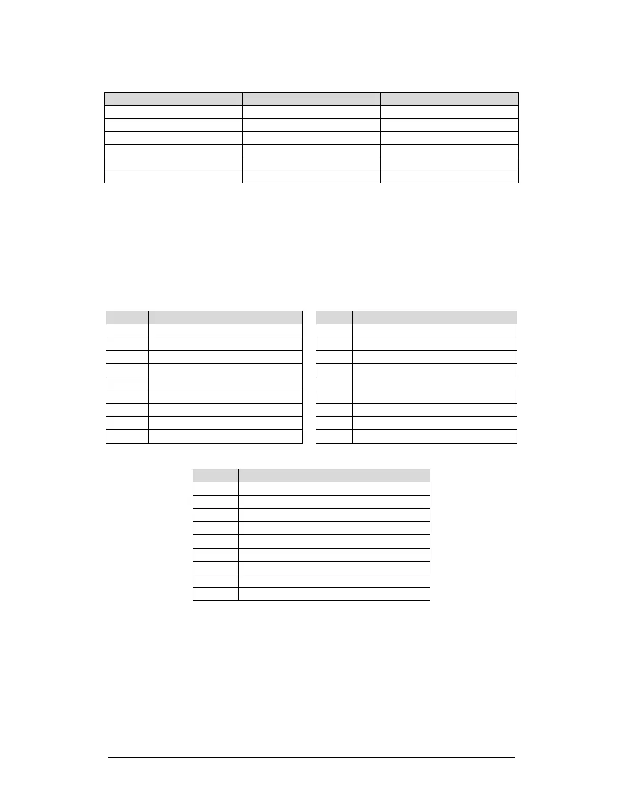
Table 4-1. ‘Ethernet’ M&C Interface Connector Pinout
Pin # Description Direction
1 Tx+ Out
3 Rx+ In
4 N/A --
6 Rx- In
Item 7 – ‘J1 | COM1’ Serial Management Utility Connector
Use this D-Sub 9-pin female (DB-9F) EIA-232/EIA-485 connector for Serial
Interface operation. The mating connector is a DB-9M connector. See Table 4-2
for the EIA-485 2-Wire pinout specification; see Table 4-3 for the EIA-485 4-Wire
pinout; and Table 4-4 for the EIA-232C pinout.
Table 4-2. ‘J1 | COM1’ 2-Wire
EIA-485 Pinout
Table 4-3. ‘J1 | COM1’ 4-Wire
EIA-485 Pinout
-Rx/Tx; Signal Complement
8 +Rx/Tx; Signal 8 +Rx; Signal
9 -Rx/Tx; Signal Complement 9 -Rx; Signal Complement
Table 4-4. ‘J1 | COM1’ EIA-232C Pinout
2 TD; Transmit Data
3 RD; Receive Data
4
5 GND; Ground
6
7