UT-4500 Series C- and Ku-Band Up Converters MN/UT4500.IOM
Front and Rear Panel Connectors Revision 3
4–12
4.2.3 Operational Connections
See Sect. 4.1 Overview – Cabling Connections Types for information
about each connector type and its connection instructions.
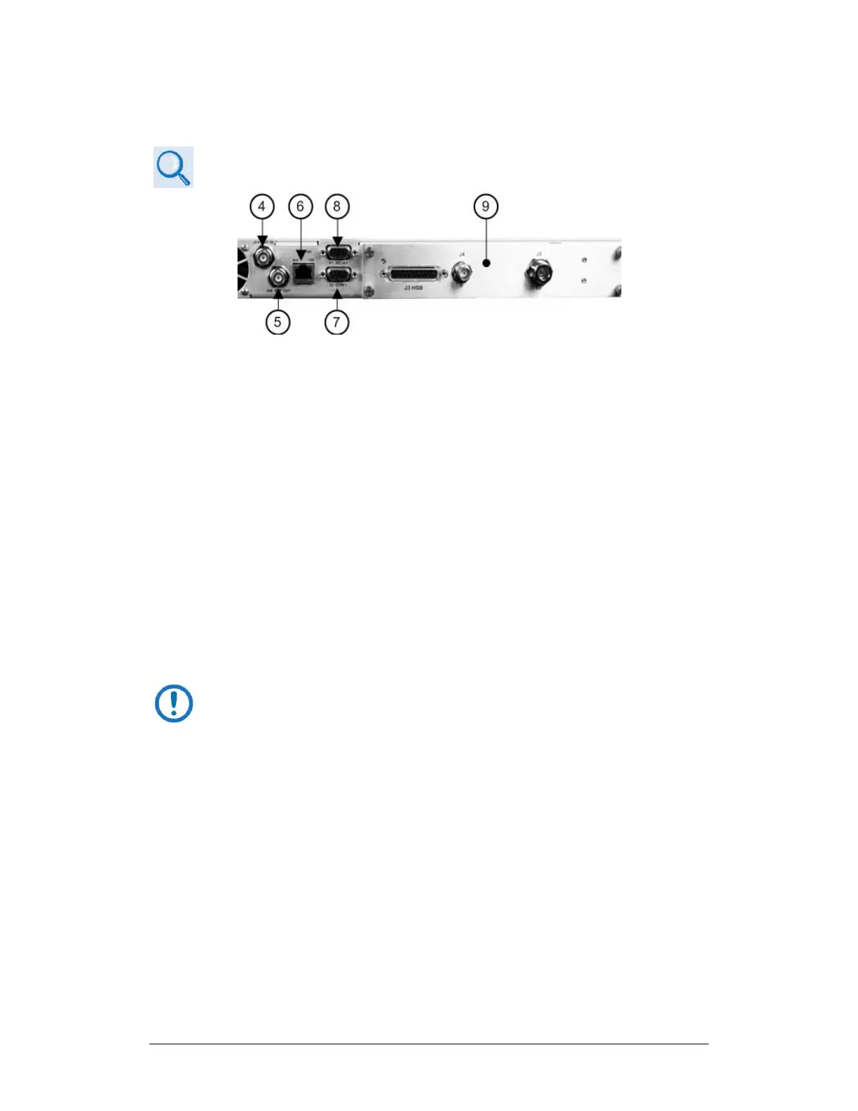
Figure 4-13. Rear Panel Operational Connections (with IOM)
As shown in Figure 4-5 and Figure 4-13 (Items 4 through 9):
Item 4 – ‘J2A | REF IN’ Utility Connector
Use this female BNC connector to supply a master reference to the entire
chassis. The user-supplied input signal is used for phase-locking the internal
10MHz reference oscillator to a user-provided 5 or 10 MHz station clock. The
impedance is matched for 50Ω or 75Ω, and requires an input level of 0 ±5 dBm.
Item 5 – ‘J2B | REF OUT’ Utility Connector (OPTIONAL)
Use this optional female BNC connector to provide a 5 or 10 MHz reference for
customer use. The impedance is matched for 50Ω or 75Ω, and provides an
output level of 5 ±3 dBm.
Item 6 – ‘Ethernet’ Ethernet Management Utility Port
The UT-4500 Series C- or Ku-Band Up Converter, as initially released,
does not feature a rear panel ‘Ethernet’ port. Only current production
units offer Ethernet Interface operation.
Use this 100BaseTX Ethernet RJ-45 port for operation of the Ethernet remote
control interfaces. It is also used for updating UT-4500 firmware. This receptacle
uses a CAT5 Ethernet cable for connection to an Ethernet hub, router, switch,
PC, etc. See Table 4-1 for the connector pinouts.