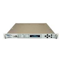
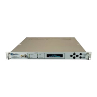
UT-4500 Series C- and Ku-Band Up Converters MN/UT4500.IOM / CD/UT4500.IOM
Table of Contents Revision 3
iv
Limitations of Warranty ................................................................................... xxiii
Exclusive Remedies.......................................................................................... xxiv
CHAPTER 1. INTRODUCTION ........................................................... 1–1
1.1 Overview .......................................................................................... 1–1
1.2 Functional Description ...................................................................... 1–2
1.2.1 Applications .......................................................................................... 1–3
1.2.2 RF Signal Conversion ............................................................................ 1–4
1.2.3 Monitor & Control ................................................................................ 1–5
1.3 Up Converter Features....................................................................... 1–6
1.3.1 Physical Description ............................................................................. 1–6
1.3.2 Dimensional Envelope .......................................................................... 1–7
1.3.3 Front Panel ........................................................................................... 1–8
1.3.4 Rear Panel .......................................................................................... 1–10
CHAPTER 2. SPECIFICATIONS ......................................................... 2–1
2.1 Physical and Environmental Specifications ......................................... 2–1
2.1.1 Regulatory Compliance ........................................................................ 2–1
2.1.2 Physical Specifications.......................................................................... 2–1
2.1.3 Mean Time Between Failures (MTBF) .................................................. 2–2
2.1.4 Temperature Range .............................................................................. 2–2
2.1.5 Humidity (Non-condensing) ................................................................. 2–2
2.1.6 Altitude ................................................................................................ 2–2
2.1.7 Front Panel Features ............................................................................ 2–2
2.1.7.1 Sample Point Connectors ............................................................. 2–2
2.1.7.2 LED Monitoring ............................................................................. 2–2
2.1.7.3 Keypad .......................................................................................... 2–3
2.1.7.4 Vacuum Fluorescent Display (VFD) ............................................... 2–3
2.1.8 Rear Panel Features ............................................................................. 2–3
2.1.8.1 Chassis Power, Fusing, and Grounding ......................................... 2–3
2.1.8.1.1 Power Supply Input ................................................................ 2–3
2.1.8.1.2 Power Consumption ............................................................... 2–3
2.1.8.1.3 Fusing ..................................................................................... 2–3
2.1.8.1.4 Grounding............................................................................... 2–4
2.1.8.2 External Reference Connectors .................................................... 2–4