Mentor ll User Guide 99
Issue Number: 12 www.controltechniques.com
Emission
For installation in the “second environment”,
ie, where the low voltage supply network does not supply domestic
premises, no filter is required in order to meet IEC61800-3 (EN61800-3).
Operation without a filter is a practical cost-effective
possibility in an industrial installation where existing
levels of electrical noise are likely to be high, and any
electronic equipment in operation has been designed
for such an environment. There is some risk of
disturbance to other equipment, and in this case the
user and supplier of the Drive system must jointly take
responsibility for correcting any problem which
occurs.
Figure 12-1 shows wiring guidelines to achieve minimum emission in a
typical installation. When used with the recommended filter the Drive
will meet the conducted emission limits required by the generic emission
standard EN50081-2.
Motor cable length should not exceed 300m to ensure that the industrial
limit is met with adequate margin.
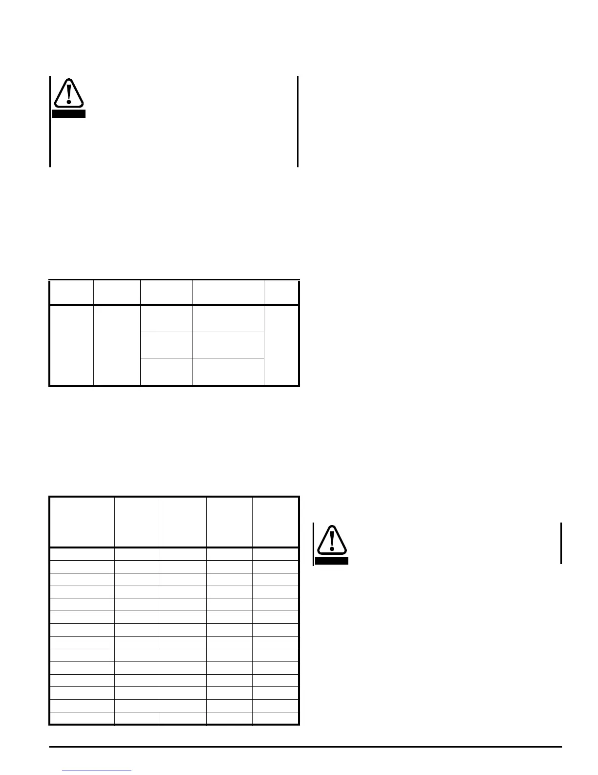
The limits for conducted emissions required by the generic standards
are summarized in the following table:
Recommended filters
Two methods are shown in Figure 12-1 for suppressing the conducted
emission into the power supply line for the main thyristor converter.
Method 1
A low cost technique using high value capacitors between power lines
and earth which makes use of the suppression provided by the standard
line reactors. Component values are given in the following table:
The capacitors must be wired in as close as possible approximation to a
‘Kelvin’ connection, minimising the length of the wiring between the
capacitors and the power circuit.
An assembly of low-inductance capacitors, designed for direct mounting
toabus-bar,isavailablefromSteatiteLtdwiththepartnumber
CON9020250. The capacitance value in this box is 10µF per phase. A
number of these assemblies can be used together to give the required
capacitance. Because of their low inductance, the next higher multiple of
10µF above the required value can be used.
The total capacitance line to earth must be within +/-10% of the value
given in the table. If lower value line reactors are used then the
capacitors must be increased in proportion. It is important that the
capacitors are rated at 440V AC and are suitable for connection to
normal industrial supplies. They should also be designed to have a low
series inductance.
Suitably rated resistors should be used to discharge the capacitors when
the supply is disconnected from the installation. The resistors given in
the table are calculated to discharge the network to less than 60V within
5s, based on a 440V supply.
The capacitor network will cause a high leakage current to flow to earth.
The leakage current may be calculated using the following expression,
assuming the three phase supply is balanced with respect to earth and
line to line:
I
E
=V × 2π × f × C × a
Where:
V is line to earth voltage
f is supply frequency
C islinetoearthcapacitance
a is capacitor tolerance.
Example: M210 Drive operating on a 400V 50Hz supply
Use 10µF+4.7µF in parallel = 14.7µF between each line and earth
(13µF is required).
Select capacitor tolerance to be 10%.
I
E
= 400 × 2π×50 ×14.7 × 10
-6
× 0.1
=185mA
In the event of a phase loss the leakage current will be higher. It can be
calculated from the following expression:
I
EPL
= V
LE
× 2π×f × C
=(400/√3) ×2π×50 ×14.7 × 10
-6
=1.07A
The capacitors cause a high earth leakage current. A
permanent fixed earth connection must be provided,
and subjected to regular testing.
If high earth leakage currents are unacceptable then an RFI filter must
be used instead of capacitors. The filter uses lower values of
capacitance, achieving the necessary attenuation by inductance.
Standard Description Frequency
range
Limits Applica-
tion
EN50081-2 Generic
emission
standard for
the
industrial
environment
0.15-0.5MHz
79dBµV quasi peak
66dBµV average
AC
supply
lines
0.5-5MHz
73dBµV quasi peak
60dBµV average
5-30MHz
73dBµV quasi peak
60dBµV average
Drive Line
reactors
La, Lb, Lc
(µH)
Line to
earth
capacitors
Ca, Cb, Cc
(µF)
Discharge
resistors
Ra, Rb, Rc
(kΩ)
Discharge
resistor
power
rating
(W)
M25, M25R 200 4.7 470 0.5
M45, M45R 200 4.7 470 0.5
M75, M75R 100 10 220 0.5
M105, M105R 100 10 220 0.5
M155, M155R 75 13 150 1
M210, M210R 75 13 150 1
M350, M350R 35 29 68 3
M420, M420R 27 37 56 3
M550, M550R 25 40 56 3
M700, M700R 23 44 47 3
M825, M825R 19 53 39 4
M900, M900R 17 59 33 4
M1200, M1200R 13 77 27 6
M1850, M1850R 8.6 116 18 9
CAUTION
WARNING