100 Mentor ll User Guide
www.controltechniques.com Issue Number: 12
Method 2
RFI filter with low leakage current to earth
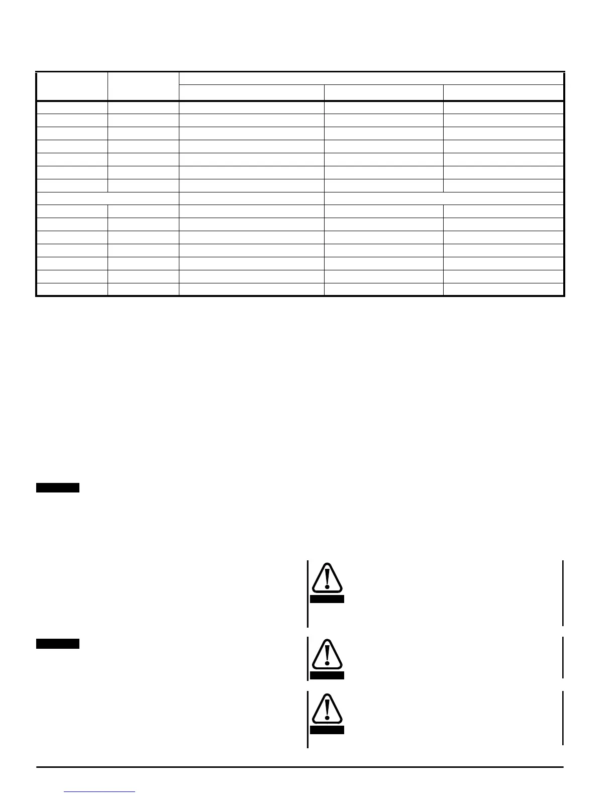
Recommended filters are shown in the following table:
• 690V version also available - add the code HV after3359 in the part
number.
Recommended filter for the field regulator
There are several possibilities depending on the main suppression and
how the Drive is connected to the system.
1) Using method 1 for the main circuit, if the capacitor network remains
in circuit at all times when the field regulator is energised, then some low
cost radio frequency chokes (L
F1
and L
F2
) can be used - refer to Figure
12-1
2) Using methods 1 or 2, if the field regulator is operated when the main
suppression is not connected (not illustrated in Figure 12-1), then a
separate RFI filter is required. The filter can be used as an alternative to
RF chokes even if the main filter remains in circuit at all times.
Mentor Drives rated above 210A are normally supplied with a
bridge rectifier to provide a fixed field. The field supply will still
require filtering using either RF chokes or separate filter listed in
the table. The FXM5 external field controller, rated at 20A, may be
filtered in a similar way using the appropriate rated components.
Refer to the Mentor II EMC datasheet.
Radiated emissions
When installed in a standard steel enclosure according to EMC
Installation Guidelines, Figure 12-1the Drive will meet the radiated
emission limits required by the generic industrial emission standard
EN50081-2.
Compliance was achieved in tests using representative enclosures
and following the guidelines given. Every effort was made to
ensure that the arrangements were robust enough to be effective
despite the normal variations which will occur in practical
installations. However no warranty is given that installations built
according to these guidelines will necessarily meet the same
emission limits.
Enclosure construction
For most installations, the Mentor Drive will be mounted in a protective
metal enclosure which may have an internal back-plate for mounting
VSD modules, RFI filters and ancillary equipment. There may be a
requirement to shield the motor cable; if this is the case, electrically bond
the shield to the back plate of the enclosure as shown in Figure 12-1
Alternatively, the shield may be bonded to the enclosure wall at the point
of cable entry using the normal gland fixings.
In some designs the enclosure wall used for cable entry may consist of
separate panels. Bonding the motor cable shield to these surfaces is
acceptable provided they make good electrical contact with the
remaining structure.
Motor cable selection
When testing the Drive module alone, it is necessary to specify the use
of a shielded cable for the motor. This is because the output of the Drive
contains radio frequency energy caused by the switching of the
thyristors. In order to meet the standards specified, if the cable were not
shieldedthenanoutputfilterwouldhavetobeusedinordertoreduce
the radio frequency voltage in the motor circuit to the level required by
the standards. This situation is the same for all DC Drives from all
manufacturers.
It is the responsibility of the owner or user to ensure
that the installation of the Drive and the way it is
operated and maintained complies with the
requirementsoftheHealthandSafetyatWorkActin
the United Kingdom and applicable legislation and
regulations and codes of practice in the UK or
elsewhere.
Safety grounding (earthing) and cabling should
conform to local codes of practice and regulations.
Safety grounding must always take precedence over
the requirements of EMC grounding.
Special consideration is needed It the filter is to be
used in movable equipment where the ground is
connected through a flexible cable and plug/socket.
Additional measures such as a supplementary ground
connection or ground continuity monitoring will be
required.
Drive Line reactors
La, Lb, Lc (µH)
RFI filter for main convertor
Control Techniques part no. 4200 - Voltage rating (V
rms
)50/60Hz
Current rating (A
rms
)at50
o
C
M25, M25R 200 1051 or 6116 440 50
M45, M45R 200 1051 or 6116 440 50
M75, M75R 100 1071 or 6117 440 70 or 63
M105, M105R 100 1111 or 6106 440 110 or 100
M155, M155R 75 1171 or 6107 440 170 or 150
M210, M210R 75 1171 or 6111 440 170 or 180
M350, M350R 35 1301 or 6115 440 300
Schaffner part no.
M420, M420R 27 FN3359-400-99
500* 400
M550, M550R 25
FN3359-600-99 500* 600
M700, M700R 23
FN3359-600-99 500* 600
M825, M825R 19
FN3359-1000-99 500* 1000
M900, M900R 17 FN3359-1000-99
500* 1000
M1200, M1200R 13
FN3359-1000-99 500* 1000
M1850, M1850R 8.6
FN3359-1600-99 500* 1600
NOTE
NOTE
WARNING
WARNING
WARNING