102 Mentor ll User Guide
www.controltechniques.com Issue Number: 12
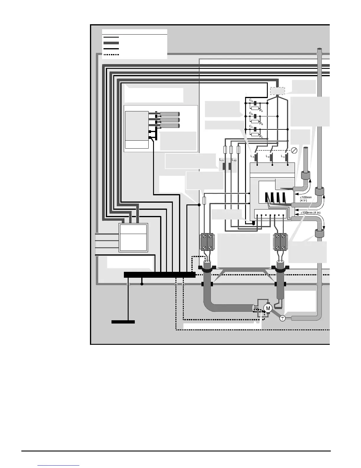
Figure12-1 EMCinstallation guidelinesforMentorII Drive
(field connections are shown for M25 to M210).
Conducted emissions from the main thyristor convertor suppressed by
line to earth capacitors and standard line reactors.
For more detailed information, refer to the Mentor II EMC datasheet.
L1
L2
L3
0V
AC supply phases and ground cables
for each Drive must be parallel and
close together
Output 3
Output 2
Output 1
Ground
Host
controller
Control
cables to
the Drives
Isolated 0V bus-bar
Bus-bar must be
isolated from the
enclosure
Power ground bus-bar
Bus-bar does not need to be
isolated from the enclosure
System isolator
AC supply
Ground
Back-plate
Safety bond
to enclosure
Site ground
(if required)
Key to symbols
Single power cable
Three-phase AC power cable
Ground cable
Alternative
location of fuses
Bond the
back-plate to the
power ground
bus-bar
Enclosure
L1 L2 L3
A1
A2
E1E2 E3F1+ F2-
MDA 2B
Bond the armour or shield to the
back-plate. If the enclosure
construction permits, you may
instead bond the armour or shield to
theenclosureatthecableentry
point. Refer to Radiated emissions in
the EMC Data Sheet.
Line-to-ground
capacitors and
discharge resistors
Drive
Safety ground
terminal
Line reactors
See signal
connections
diagrams
If an optional MD29
card is installed, fit a
ferrite ring Part No.
3225-1004 around all
control cables that
connect to the card
Fit a ferrite ring
Part No. 3225-1004
around all control cables
that connect to the
control card
Control
card
Optional
MD29 card
RF chokes for the field regulator
Alternatively an RFI filter (shown
opposite) can be used
Alternative ground connection
Some applications may
requireaDCfuseinthe
armature circuit. Refer to
the Mentor User Guide.
Alternative safety ground connections for the motor
Alternatively, an
encoder may be
used for speed
feedback
AC supply
distribution
and fuses