Mentor ll User Guide 103
Issue Number: 12 www.controltechniques.com
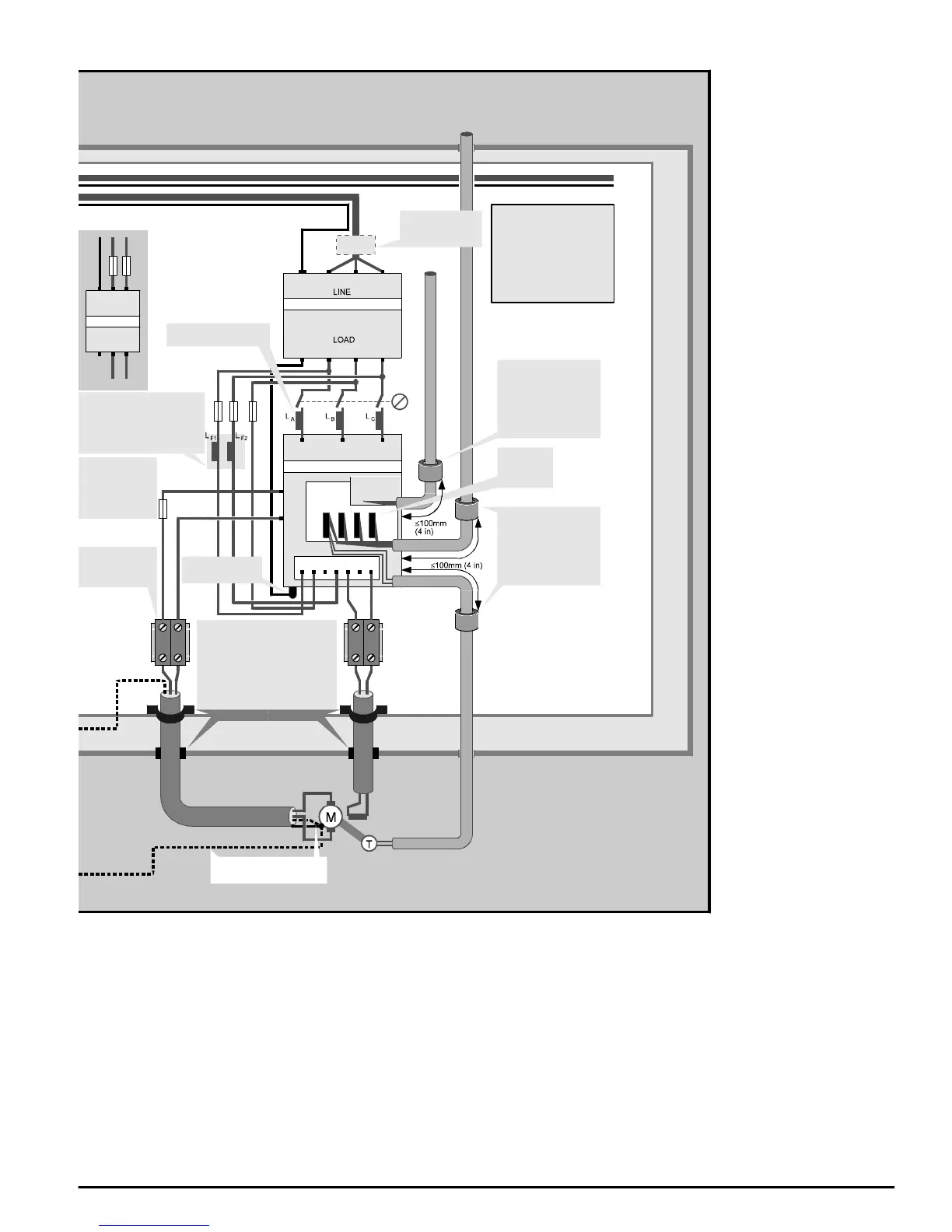
L1 L2 L3
A1
A2
L3 L2 L1
L3 L2 L1
Example
connections
using a DIN-rail
connector
RFI filter
Drive
Back-plate
Enclosure
E1E2 E3F1+ F2-
MDA 2B
Control
card
PE
PE
Alternative location
of fuses
Safety ground
terminal
Optional
MD29 card
See signal
connections
diagrams
If an optional MD29 card is
installed, fit a ferrite ring
Part No. 3225-1004
around all control cables
that connect to the card
Line reactors
RF chokes for the field
regulator
Alternatively an RFI filter (shown
above) can be used (refer to the
EMC data sheet)
φ2 φ1
φ2 φ1
E
E
LINE
LOAD
Bond the armour or shield to the
back-plate. If the enclosure
construction permits, you may
instead bond the armour or shield to
the enclosure at the cable entry point.
Refer to Radiated emissions in the
EMC Data Sheet.
Fit a ferrite ring
Part No. 3225-1004
around all control cables
that connect to the control
card
Some applications
may require a DC
fuse inthe armature
circuit. Refer to the
Mentor User Guide.
RFI filter
Alternative safety ground
connections for the motor
Refer to the EMC Data Sheet
for information on the following:
Line-to-ground capacitors
and discharge resistors
Line reactors
RF chokes for the field
regulator
RFI filters