Mentor ll User Guide 49
Issue Number: 12 www.controltechniques.com
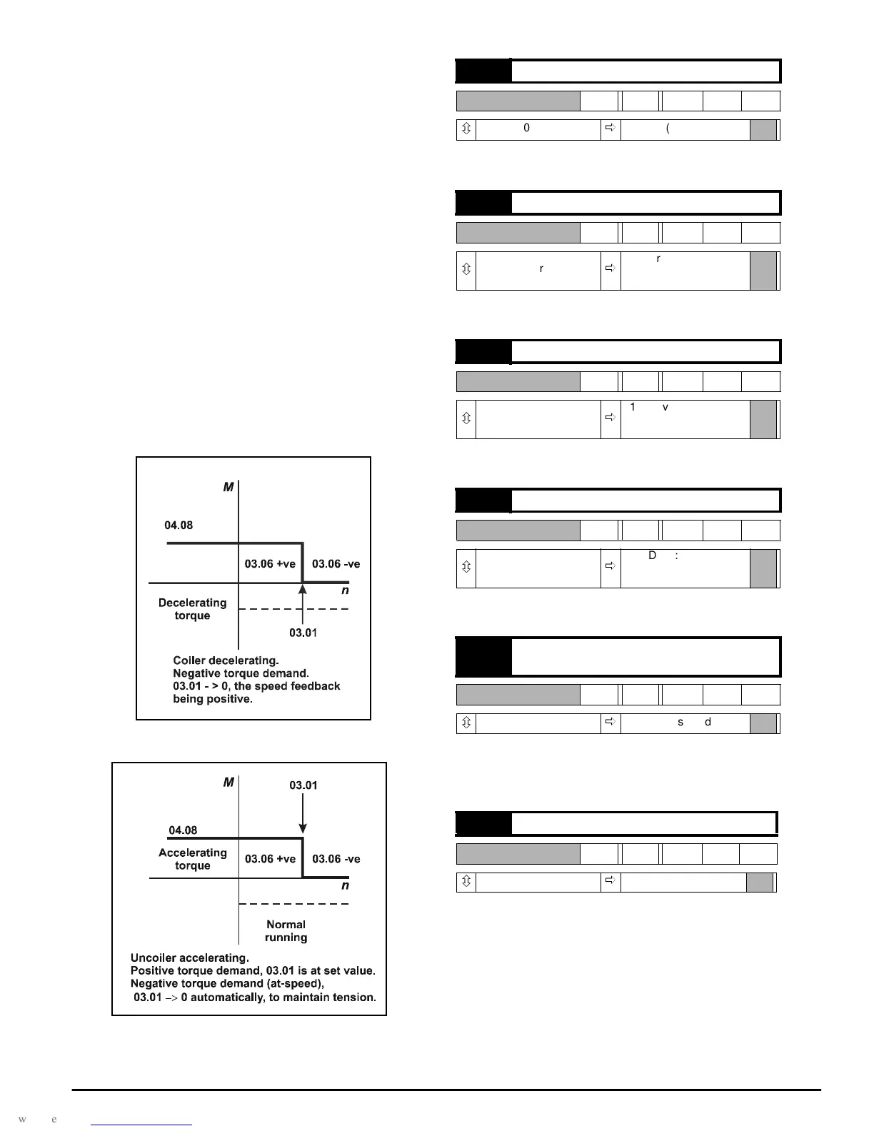
Coiler/uncoiler control mode
Refer to Figure 8-4 and Figure 8-5.
This mode allows torque to be applied in either sense, for acceleration or
deceleration, while preventing uncontrolled increase in speed or
reversal if the load becomes zero. When the torque demand is in the
sense opposite to that of speed
feedback, this mode automatically selects zero speed reference.
For a coiler, the offset 01.04 should be set just slightly positive so that
03.01 is greater than the line speed reference. When a full reel (of a
coiler) is decelerating, the torque demand may be negative. Since the
speed feedback is positive, the speed reference is automatically made
zero so that the speed errorbecomes negative. Both torque demand and
speed error being negative, decelerating torque is applied.
For an uncoiler, the offset 01.04 should be set just slightly negative so
that there is a negative speed error at zero speed. (Negative speed error
is necessary to produce a negative torque to maintain tension at zero
speed.) As the line speed reference increases, 03.01 becomes positive.
A suitable scaling ofthe input should be applied such that 03.01 is always
greater than the speed feedback, thus maintaining a positive speed error
03.06. Since the speed feedback is positive, zero speed is automatically
selected whenever the torque demand is negative normal operation but
if the torque demand becomes positive then the value of 03.01 becomes
the speed demand, and accelerating torque is allowed, provided that the
reel speed is not greater than 03.01.
For coiler/uncoiler applications, line speed reference corresponds to reel
speed at minimum diameter.
Figure 8-4
Figure 8-5
Quadrant 1 operation is defined as motoring in the forward direction,
speed and torque both having positive values.
Quadrant 2 operation is defined as regenerating in the reverse direction,
speed being negative and torque positive.
Quadrant 3 operation is defined as motoring in the reverse direction,
speed and torque both having negative values.
Quadrant 4 operation is defined as regenerating in the forward direction,
speed being positive and torque negative.
When this bit is enabled, the current limit bridge 2 selector is
automatically changed to 1 after a time interval set by 04.19.TheDrive
can be programmed to select 04.07 automatically at a programmed
time-interval (04.19)afteraRUNsignal.
A time interval up to 255 seconds can be programmed. If 04.18 =1,
current limit bridge 2 is automatically selected when the set time elapses
after a RUN command. This feature is appropriate to applications where
the motor is short-time rated, such as mixing machinery, where the
starting load is high and falls to a lower, constant value only after the
machine has run for some time.
04.14 Quadrant 1 enable
RW Bit
ô
0or1
ð
1 (enabled)
04.15 Quadrant 2 enable
RW Bit
ô
0or1
ð
1Q Drive: 0 (disabled)
4Q Drive: 1 (enabled)
04.16 Quadrant 3 enable
RW Bit
ô
0or1
ð
1Q Drive: 0 (disabled)
4Q Drive: 1 (enabled)
04.17 Quadrant 4 enable
RW Bit
ô
0or1
ð
1Q Drive: 0 (disabled)
4Q Drive: 1 (enabled)
04.18
Enable automatic current limit bridge 2
change
RW Bit
ô
0or1
ð
0 (disabled)
04.19 Current limit timer
RW Uni
ô
0~255
ð
000