56 Mentor ll User Guide
www.controltechniques.com Issue Number: 12
The minimum value of current demand, to prevent excessive field
weakening, for example with overhauling loads.
Parameter 06.11 permits the user to apply a scaling factor to the current
feedback. Output is the value 06.03. The max. current rating is 2A or 8A
according to the position of link (jumper) J1.
MentorIIcanbeusedwithanIssue(rev)1MDA3card,maximum
current 5A. Parameter 06.11 then has the range 101 to 110 and a
field current range from 0.5A to 5A in steps of 0.5A.
Field control can alternatively be implemented by the FXM5 Field
Control Unit (Chapter 9) for a maximum field current of 20A.
Permits the Drive to be configured to select maximum field 2 (a reduced
setting) automatically after the Drive has been disabled for a period (in
seconds) defined by the value chosen for this parameter. Provided so
that the windings do not overheat if the Drive is stopped and the motor
ventilation is switched off, or to maintain a reduced level of field current
to prevent condensation when the motor is not in use.
Set to 1 to engage maximum field 2. Controlled automatically by field
economy timeout function if 06.15 is set to 1. Maximum field 2 is
selected after a time delay (refer to 06.12) when a Drive disable signal is
given.
When enabled (=1), parameter 06.14 is automatically controlled by the
field economy timeout function when a Drive enable signal is removed.
When the timeout is disabled, parameter 06.14 becomes user RW.
When set to = 0, the field current loop integral gain is increased to allow
the loop to track the current demand more closely. However, this may
result in instability and so should only be used if a fast change in flux is
required and the field time-constant is low.
Set 06.17 = 1 to double the integral gain if less overshoot is desired.
This parameter adjusts the speed loop gains (menu 03) to compensate
for the weakening of the field flux in field control mode so that the torque
response remains substantially constant throughout the whole speed
range.
Defined as:
Where:
G = Speed loop gain adjustment factor
Enables 06.09 to control the firing angle directly, subject only to the front
endstop. Permits operation without the voltage or the current loop, for
the purpose of diagnosis.
In this mode there is no protection against excessive field voltage
and current.
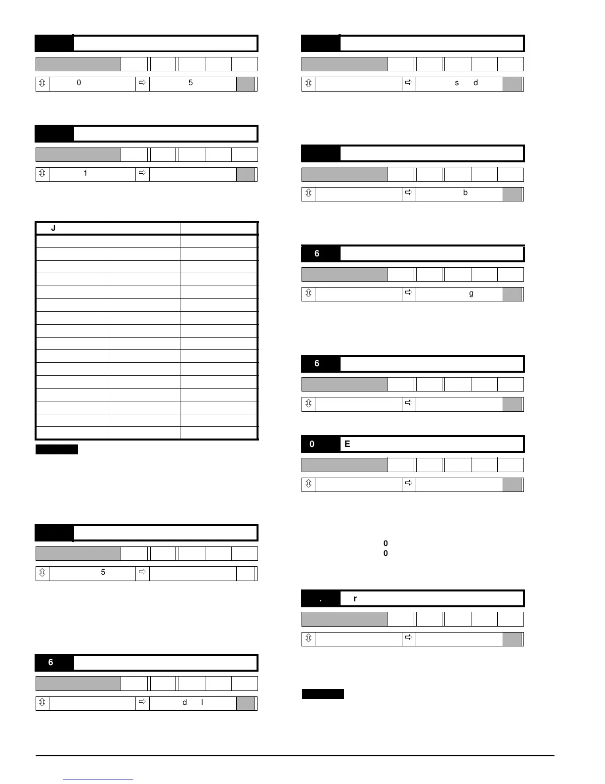
06.10 Minimum field current
RW Uni
ô
0 ~ 1000
ð
+500
06.11 Field current feedback scaling
RW Uni
ô
201 ~ 216
ð
204
J1 position 06.11 setting MDA3 amps max.
2A 201 0.5
2A 202 1.0
2A 203 1.5
2A 204 2.0
8A 205 2.5
8A 206 3.0
8A 207 3.5
8A 208 4.0
8A 209 4.5
8A 210 5.0
8A 211 5.5
8A 212 6.0
8A 213 6.5
8A 214 7.0
8A 215 7.5
8A 216 8.0
06.12 Field economy timeout
RW Uni
ô
0~255
ð
030 S
06.13 Enable field control
RW Bit
ô
0or1
ð
0, disabled
NOTE
06.14 Maximum field 2 selector
RW Bit
ô
0or1
ð
0, disabled
06.15 Enable field economy timeout
RW Bit
ô
0or1
ð
0, disabled
06.16 Field current loop integral gain
RW Bit
ô
0or1
ð
1, normal gain
06.17 Voltage loop integral gain
RW Bit
ô
0or1
ð
0, disabled
06.18 Enable speed gain adjustment
RW Bit
ô
0or1
ð
0, disabled
06.19 Direct firing angle control
RW Bit
ô
0or1
ð
0, disabled
G
06.08
06.02
---- ---- --- ----
=
NOTE