60 Mentor ll User Guide
www.controltechniques.com Issue Number: 12
Sets the scaling for signals from the reference encoder (pulse tach.)
connected to terminal socket PL4. The value should be set to
correspond with the maximum speed of the motor and with the number
of pulses-per-revolution of the encoder.
To calculate the scale factor:
Where:
N = number of pulses per revolution
n = max speed of motor in rpm.
Default value is determined on the basis of a 1024-line encoder (pulse
tach.), and a maximum speed of 1750rpm. Maximum frequency for the
encoder is 105kHz.
0 = analog reference selected.
1 = encoder (pulse tach.) selected.
Selects either the analog signal at terminal TB1-03 or the encoder (pulse
tach.) input via PL4 as the source of speed reference signal.
Configures the speed input terminal (TB1-03) to accept either a voltage
or a 20mA input signal.
In conjunction with 07.28, configures 20mA current loop input.
In conjunction with 07.27, configures 20mA current loop input.
When a 4mA offset is being used, the Drive will trip if it senses that the
current is <3.5mA indicating loop open.
When set to 1 the polarity of GP3 and GP4 analog inputs will be
inverted.
The value of 07.03 and 07.04 are not affected and will indicate the
polarity of the voltage applied to terminals TB6 and TB7.
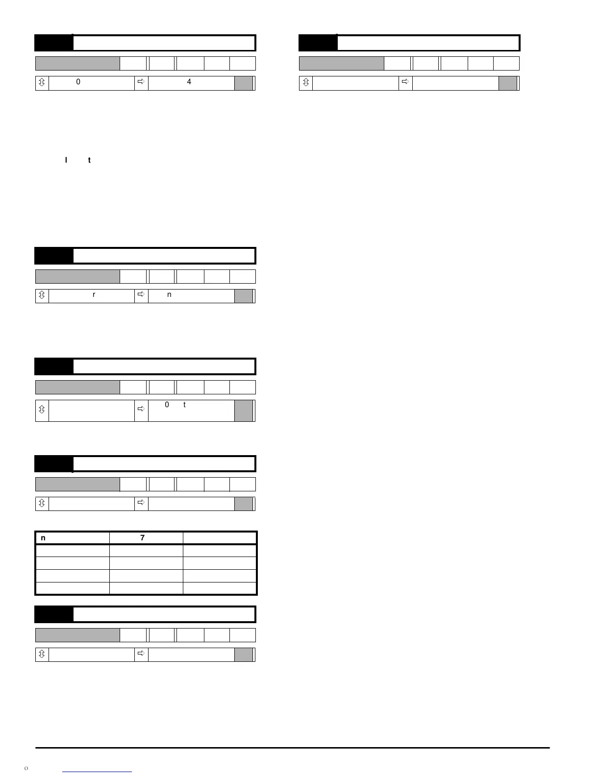
07.24 Reference encoder scaling
RW Uni
ô
0 ~ 1999
ð
+419
07.25 Encoder reference selector
RW Bit
ô
0or1
ð
0, analog ref.selected
07.26 Current input selector
RW Bit
ô
0or1
ð
0, voltage input
selected
07.27 Current sense inverter
RW Bit
ô
0or1
ð
0
Input 07.27 07.28
0-20mA 0 0
20-0mA 1 0
4-20mA 0 1
20-4mA 1 1
07.28 4mA offset selector
RW Bit
ô
0or1
ð
0
ScaleFactor
750 10
6
()×
Nn×
------------------------------
=
07.29 Invert GP3 and GP4 analog inputs
RW Bit
ô
0or1
ð
0