62 Mentor ll User Guide
www.controltechniques.com Issue Number: 12
0=disable
1 = enable
Monitors the Drive enable input from terminal TB4-31 and indicates
status. Input must be active for the Drive to operate. When the Drive is
disabled by disconnecting the input, all firing pulses are switched off
after a 30ms delay. If the Drive is running when this occurs, the result is
a coast-stop and ramps reset.
Defines the destination of external logic input at terminal TB3-22.
Effective only after RESET.
Defines the destination of external logic input at terminal TB3-23.
Effective only after RESET.
Defines the destination of external logic input at terminal TB3-24.
Effective only after RESET.
Defines the destination of external logic input at terminal TB3-25.
Effective only after RESET.
Defines the destination of external logic input at terminal TB3-26.
Effective only after RESET.
Defines the destination of external logic input at terminal TB3-27.
Effective only after RESET.
Defines the destination of external logic input at terminal TB3-28.
Effective only after RESET.
Defines the destination of external logic input at terminal TB3-29.
Effective only after RESET.
Defines the destination of external logic input at terminal TB3-30.
Effective only after RESET.
0 = enable normal logic function
1 = disable normal logic function
Default 0
If set to enable (= 0), this parameter configures logic inputs in the
following manner:
F2 TB3-22Inch Reverse
F3 TB3-23Inch Forward
F4 TB3-24Run Reverse
F5 TB3-25Run Forward
If set to disable (=1), the logic inputs must be programmed by the user. A
programmable input can be used to control parameter 1.11(Reference
ON) only if a RUN PERMIT signal is present.
See also parameters 08.31 to 08.34.
SerialcommunicationscanbeusedtocontroltheDrivewhennormal
logic functions are disabled by writing to paramters 1.11, 1.12 and 1.13.
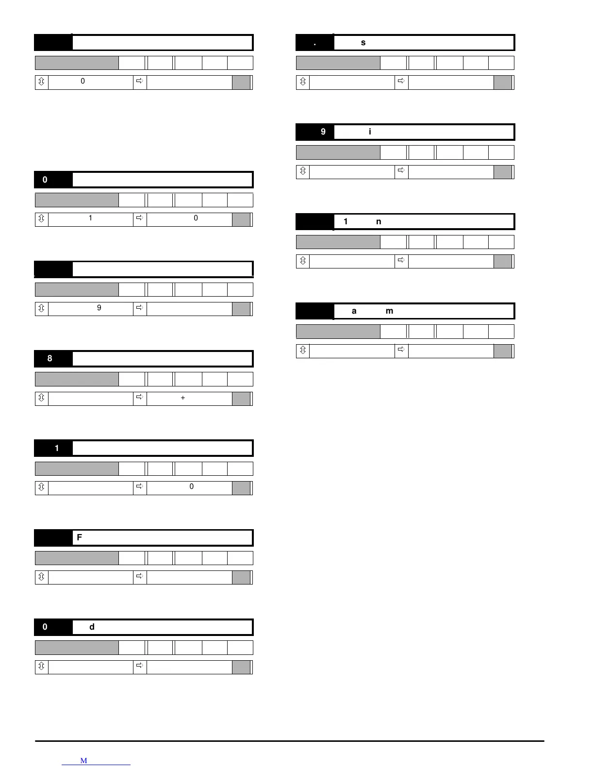
08.11 Enable input
RO Bit
ô
0or1
ð
0
08.12 F2 destination
RW Uni
ô
0 ~ 1999
ð
+000
08.13 F3 destination
RW Uni
ô
0 ~ 1999
ð
+000
08.14 F4 destination
RW Uni
ô
0 ~ 1999
ð
+000
08.15 F5 destination
RW Uni
ô
0 ~ 1999
ð
+000
08.16 F6 destination
RW Uni
ô
0 ~ 1999
ð
+000
08.17 F7 destination
RW Uni
ô
0 ~ 1999
ð
+000
08.18 F8 destination
RW Uni
ô
0 ~ 1999
ð
+000
08.19 F9 destination
RW Uni
ô
0 ~ 1999
ð
+000
08.20 F10 destination
RW Uni
ô
0 ~ 1999
ð
+000
08.21 Disable normal logic functions
RW Bit
ô
0or1
ð
0