Chapter 5 Running Mode And Controlling Wiring
5.1 Position Control Mode
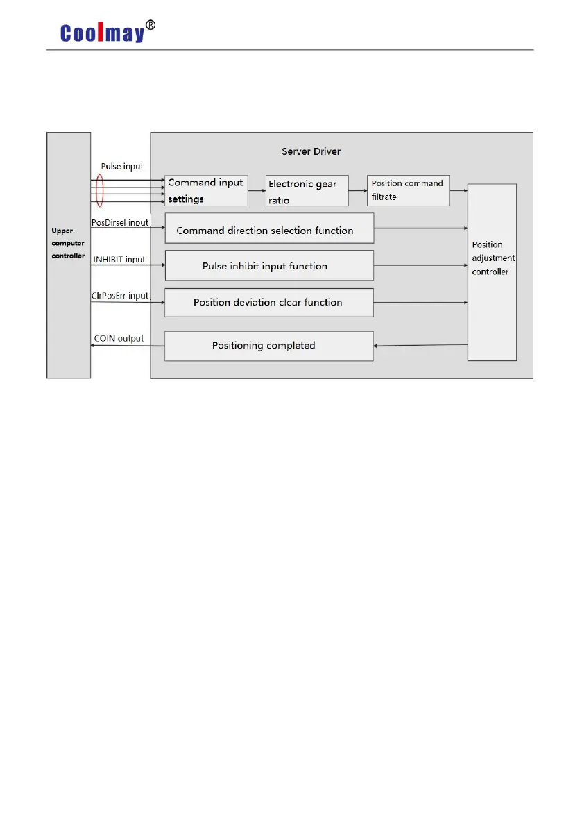
5.1.1 Position Mode Introduction
Pic 5.1 Position Mode Diagram
The main steps for position mode are as follows:
1) Correctly connect the main circuit and the power supply , as well as the motor power cable
and encoder cable. After powering on, the drive panel displays "r 0" ,which means that the
drive power supply and encoder wiring are correct.
2) Pressing the keys for servo JOG trial operation to confirm whether the motor can run
normally.
3) To connect the pulse direction input and pulse instruction input of the CN1 terminal as well
as the required DI/DO signals, such as servo enable, alarm clearance, location completion signal,
etc based on the figure 5.2 as a reference.
4) Then to make some setting operations. DI/DO can be set according to actual situation.
5) For servo enable, the servo motor rotation is controlled by the position instruction from the
upper computer. Firstly make the motor rotate at low speed, and confirm whether the rotation
direction and electronic gear ratio are normal, then make the gain adjustment.
5.1.2 Position Mode Wiring