Chapter 5 Running Mode And Controlling Wiring
Hysteresis For Zero Speed
Detection
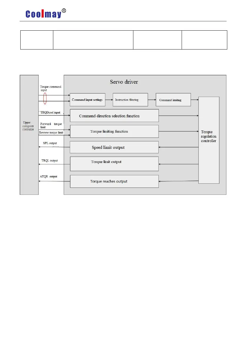
5.3 Torque Control Mode
5.3.1 Introduction
Pic 5.5 Torque Control Mode
The main steps to use the speed control mode are as follows:
1) Correctly connect the servo main circuit and the power supply of the controller, as well as
the motor cable and encoder cable. The servo panel displays”r 0” after powering on which
means that the servo power supply and encoder connection are correct.
2) Operate the servo JOG trial running mode through the panel keys to confirm whether the
motor can run normally.
3) To connect the required DI/DO signals in CN1 terminal, such as servo enable, alarm
clearance, positioning completion signal, etc referring figure 5.4.
4) To operate torque mode related setting. DI/DO are used to set according to your
application.
5) To make the servo enabled and the servo motor rotation is controlled by the position
instruction issued by the upper computer. First make the motor rotate at low speed, and confirm