Chapter 4 Drive System Wiring And Introduction
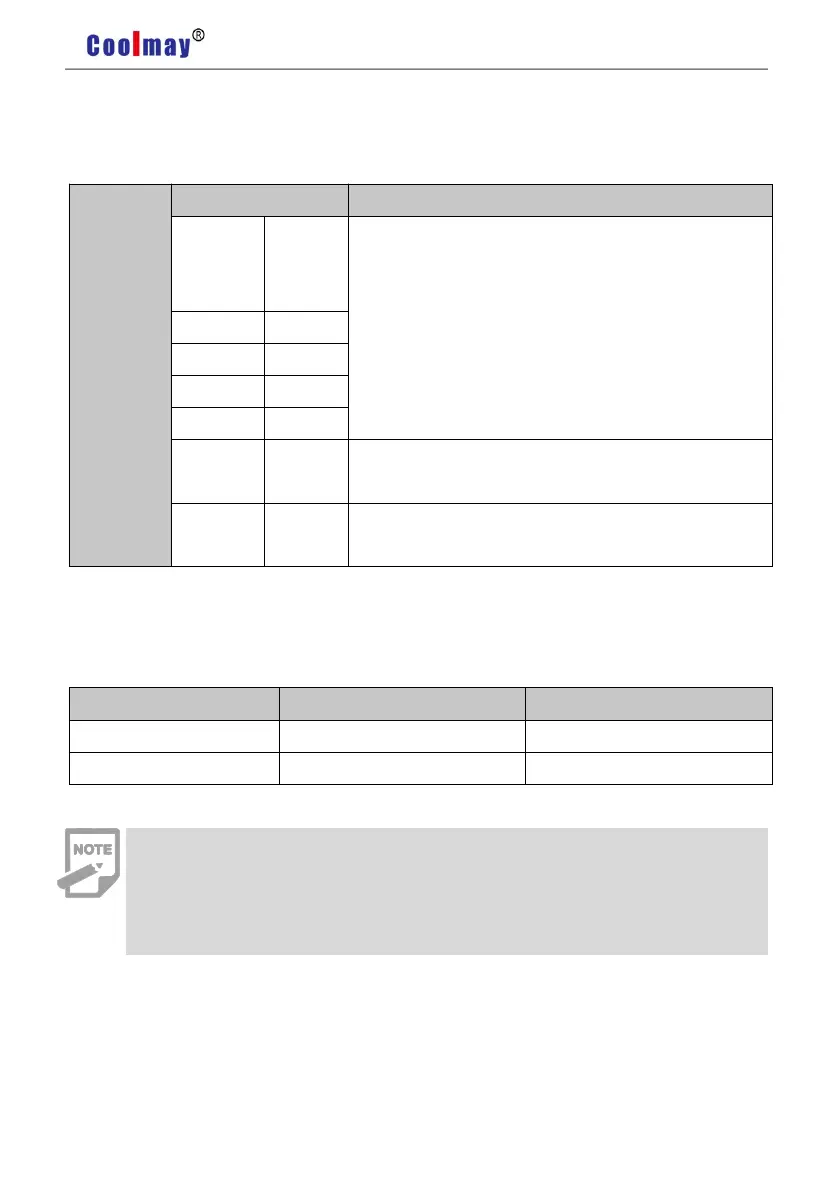
Pic 4.5 CN1 Terminal
4.4.3 Position Instruction Input Signal
High speed photo isolation input.
Working mode is set by parameter FA14:
Pulse+direction.
CCW/CW pulse.
A、B orthogonal pulse input.
Input of internal position control.
External 24V power input interface of the instruction
pulse.
Internal digital signal ground.
The output circuit of instruction pulse of the upper device side can be selected from the
differential output or collector open circuit output . Its maximum input frequency and minimum
pulse width are shown in the following table:
If the output pulse width of the upper device is less than the minimum pulse
width, it will cause the drive to receive error pulses.
The terminal between PULS+ and PULS-/SIGN+ and SIGN- only support
below 5V signal. If over than 5V, it needs to connect external resistances.