Do you have a question about the Copystar CS-2030 and is the answer not in the manual?
Explains warning symbols for danger, caution, and prohibition.
Lists general specifications of the copier.
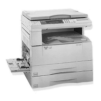
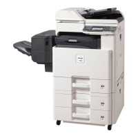
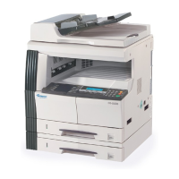
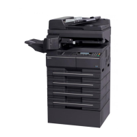
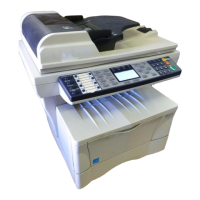
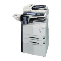
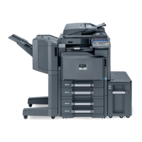
Identifies and describes key copier parts.
Illustrates the internal structure of the machine.
Explains the drive system components.
Details the procedure for unpacking the machine.
Covers paper misfeed indications, conditions, and causes.
Details common image formation issues and their troubleshooting.
Lists electrical issues, causes, and corrective measures.
Covers mechanical problems and their troubleshooting.
Explains how to enter and execute maintenance items.
Details procedures for assembly and disassembly.
Explains the self-diagnostic function and codes.
Outlines safety precautions for disassembly and assembly procedures.
Details procedures for detaching and refitting paper feed components.
Details procedures for detaching and refitting the exposure lamp and scanner wires.
Details procedures for detaching and refitting the charger assembly.
Details procedures for detaching and refitting the drum.
Details procedures for adjusting the doctor blade position.
Details procedures for detaching and refitting the transfer roller assembly.
Details procedures for detaching and refitting the cleaning blade and drum separation claws.
Details procedures for detaching and refitting the fixing unit and its components.
Provides instructions for replacing the main PCB, including data backup.
Details the process for upgrading firmware on the main PCB.
Instructions for upgrading firmware on the operation unit PCB for 20 cpm models.
Lists variable resistors that are factory-set and not adjustable.
Describes the mechanical construction of the machine.
Lists and identifies the main PCBs in the machine.
Explains the block diagram and functions of the power source PCB.
Explains the block diagram and functions of the main PCB.
Explains the block diagram and functions of the CCD PCB.
Explains the block diagram and functions of the laser diode PCB.
Timing chart for main switch on to machine stabilization.
Timing chart for scanner initialization.
Lists periodic maintenance tasks and their procedures.
Provides wiring diagrams for electrical components.
| Functions | Print, Copy, Scan, Fax |
|---|---|
| Print Resolution | 600 x 600 dpi |
| Copy Resolution | 600 x 600 dpi |
| Scan Resolution | 600 x 600 dpi |
| Standard Paper Capacity | 250 sheets |
| Max Paper Size | A4 |
| Interface | USB 2.0 |
| Memory | 32 MB |
| Fax Modem Speed | 33.6 kbps |
| Type | Laser |
| Copy Speed | 20 cpm |
| Connectivity | USB |
| Print Speed (Black) | 20 ppm (A4) |