3B1
1-2-5
1-2-3 Installing the optional add-on memory
Add-on memory installation on the fax control PCB assembly requires the following parts:
8 MB add-on memory (P/N: 2AW6001)
<Procedure>
1. Turn the main switch off and disconnect the power
plug from the wall outlet.
2. Remove the two screws holding the rear cover and
then the cover.
3. Remove the five screws holding the fax shield cover
and then the cover.
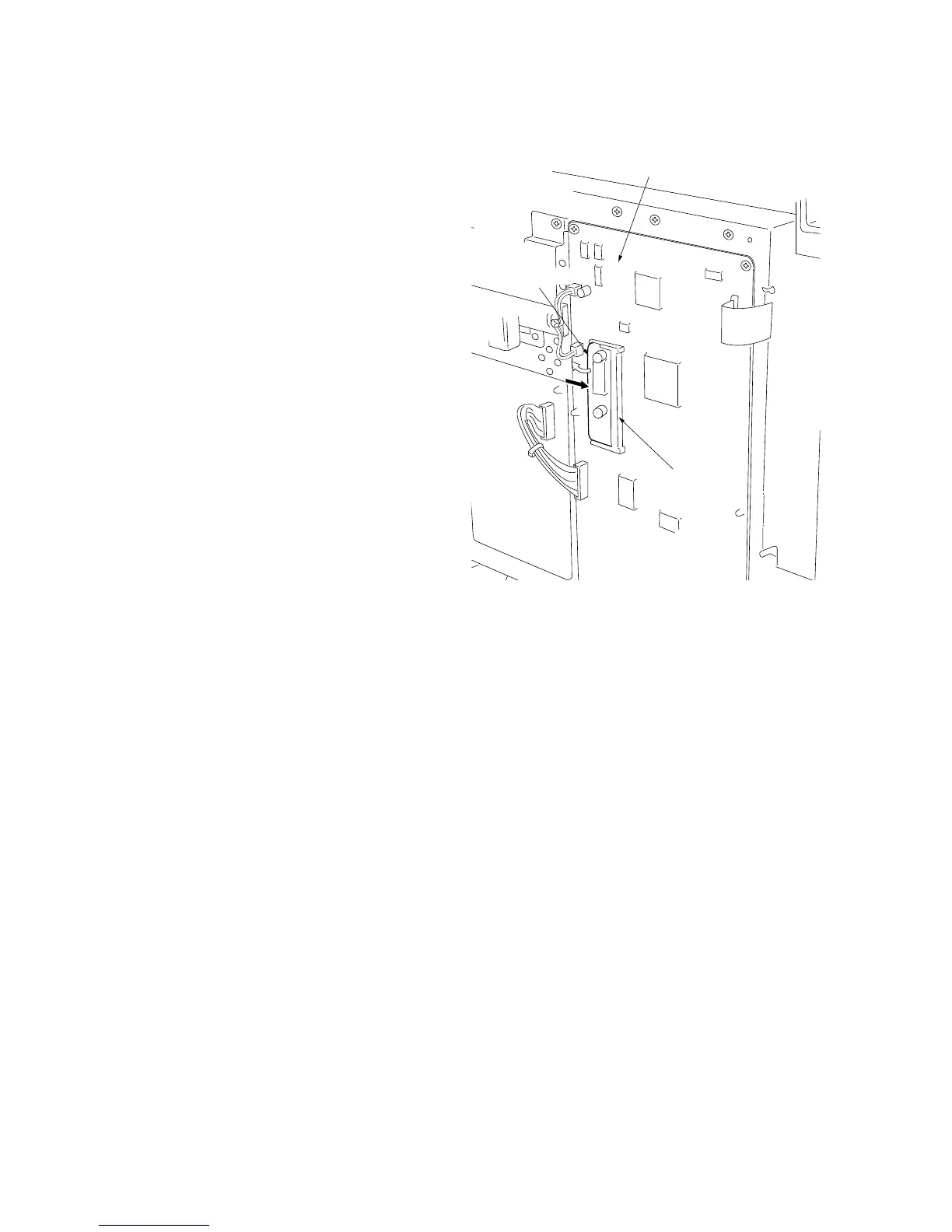
4. Insert the add-on memory into CN4 on the fax control
PCB.
*Holding the add-on memory by the sides, insert it
into the socket as shown in the diagram, and then
push it in the direction of the arrow until it clicks into
place.
5. Refit all removed parts.
Figure 1-2-2
CN4
Fax control PCB
Add-on memory