3B1
1-2-1
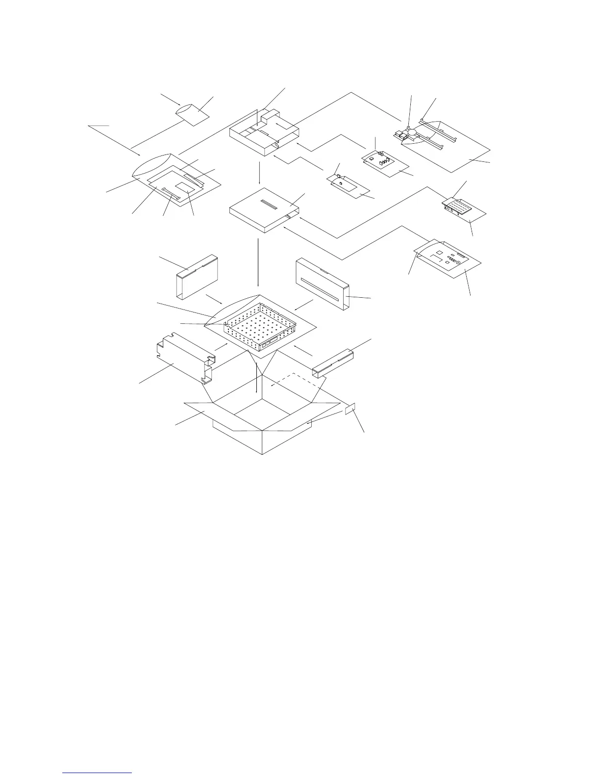
1-2-1 Unpacking
&¤‹›
fifl‡
*()⁄
°·‚
Œ
9
@
!
$
Á
^
%
‰
„
Ø
ˇ
´
5
4
2
3
9
8
7
1
2
6
2
ˆ
0
#
¨
Figure 1-2-1
1 NCU PCB assembly
2 Antistatic air-padded bags
3 Fax operation unit
4 Fax control PCB assembly
5 Antistatic air-padded bag
6 Auxiliary power source PCB
7 Speaker unit
8 Lower fax retainer
9 Plastic bags
0 Fax cable
! NCU cable
@ Instruction handbook*
1
# Installation manual
$ One-touch key sticker
% Fax shield cover
^ Plastic bag
& Modular connector cover
* Modular jack cover
( Bronze binding screw BVM3 × 05
) TP screw M3 × 05
⁄ Spacers
¤ Fax unit label sheet
‹ FCC68 label*
2
› FCC68C label*
2
fi IC line label*
2
fl Language indication label*
3
‡ Modular connector cable B*
2
° Core 7-15 × 18*
3
· Core 27-31 × 12*
3
‚ Board supports
ΠPlastic bag
„ Outer case
´ Right pad
‰ Left pad
ˇ Front pad
Á Rear pad
¨ Upper spacer
ˆ Lower spacer
Ø Barcode labels
*1: For 120 V specifications and Asia and
Oceania specifications only.
*2: For 120 V specifications only.
*3: For 220 - 240 V specifications only.
 Loading...