3A6
1-2-1
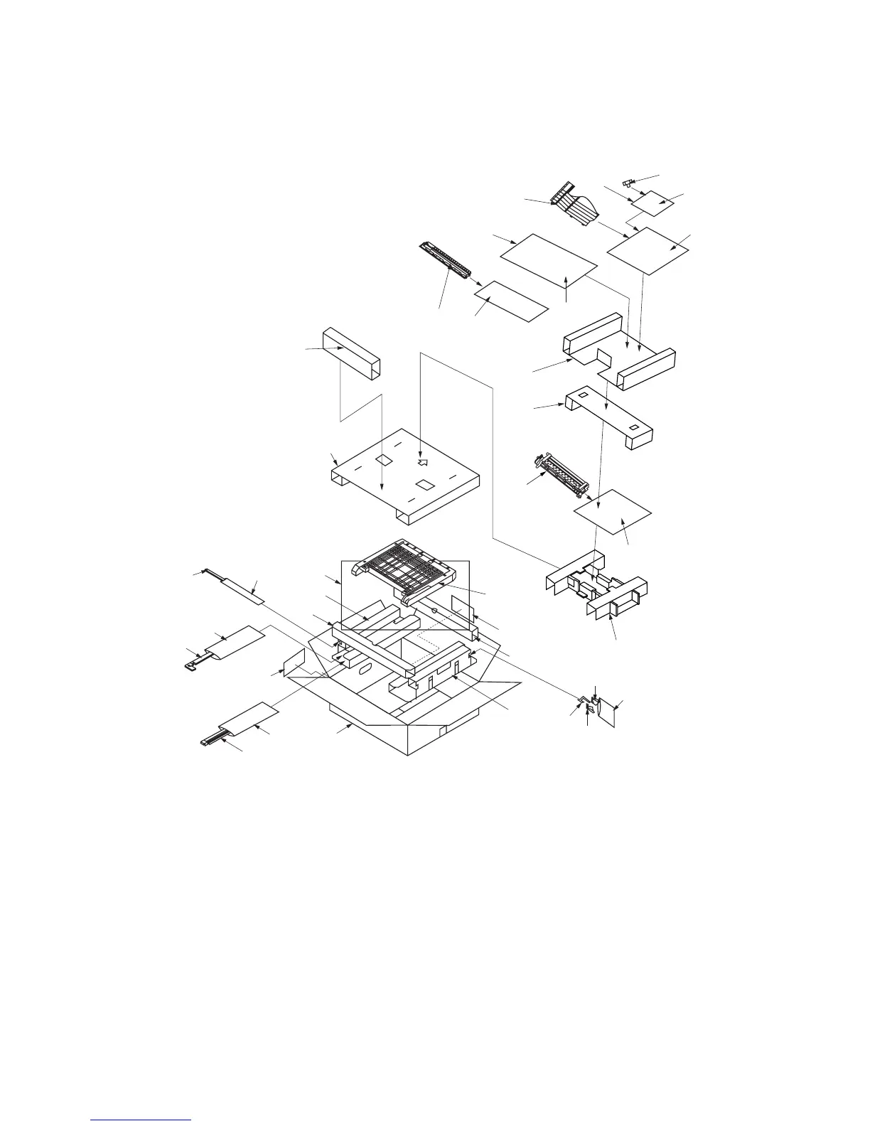
1-2-1 Unpacking
Figure 1-2-1 Unpacking
3
¨
8
‰
‰
9
Ø
5
7
4
6
°
‚
Á
fl
‡
ˆ
·
fl
‡
ˆ
2
!
@
)⁄
¤
´
‹
›
fi
#
„
(
%^
0$
&*
ˇ
1
∏
Œ
1 Feedshift unit
2 Duplex unit
3 Duplex joint
4 Front duplex fulcrum plate
5 Rear duplex fulcrum plate
6 Front fulcrum hook
7 Duplex stopper
8 Left cover
9 Entry guide
0 Two (2) stoppers 5
! Right eject cover
@ Job separator tray
# Pin
$ Two (2) cross-head bronze binding
screws BVM3 × 05
% Seven (7) cross head chrome binding
screws M3 × 14
^ One (1) cross-head chrome TP-A
screw M3 × 05
& One (1) cross-head tap-tight P chrome
TP-A screw M3 × 08
* One (1) cross-head tap-tight P chrome
TP-A screw M4 × 12
( Clamp
) Jam correction label
⁄ Eject section static eliminator
¤ Installation manual
‹ Upper pad
› Spacer
fi Plastic bag
fl Bottom pad
‡ Spacers
— Upper pad
· Outer case
‚ Spacer
ΠBottom pad
„ Plastic bag
´ Plastic bag
‰ Plastic bags
ˇ Plastic bag
Á Product cover
¨ Air-padded bag
ˆ Bar-code label
Ø Air-padded bag
” Plastic bag


 To Next Page