1-1-1
3B1
CONTENTS
1-1 Specifications
1-1-1 Specifications ....................................................................................................................................... 1-1-1
1-1-2 Parts names and their functions ........................................................................................................... 1-1-2
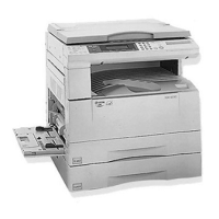
(1) Copier ........................................................................................................................................... 1-1-4
(2) Operation panel ............................................................................................................................ 1-1-5
1-1-3 Machanical construction ....................................................................................................................... 1-1-8
1-2 Installation
1-2-1 Unpacking ............................................................................................................................................ 1-2-1
1-2-2 Setting and registering data ................................................................................................................. 1-2-2
(1) Settings ......................................................................................................................................... 1-2-2
(2) Registration ................................................................................................................................... 1-2-4
1-2-3 Installing the optional add-on memory ................................................................................................. 1-2-5
1-2-4 Installing the handset (optional for 120 V specifications only) ............................................................. 1-2-6
1-3 Maintenance Mode
1-3-1 Maintenance mode ............................................................................................................................... 1-3-1
(1) Maintenance mode item list .......................................................................................................... 1-3-1
(2) Contents of maintenance mode items .......................................................................................... 1-3-4
1-4 Error Code
1-4-1 Error codes ........................................................................................................................................... 1-4-1
(1) Error code ..................................................................................................................................... 1-4-1
(2) Table of general classification....................................................................................................... 1-4-2
(2-1) U004XX error code table ...................................................................................................... 1-4-4
(2-2) U006XX error code table ...................................................................................................... 1-4-4
(2-3) U008XX error code table ...................................................................................................... 1-4-5
(2-4) U009XX error code table ...................................................................................................... 1-4-5
(2-5) U010XX error code table ...................................................................................................... 1-4-6
(2-6) U011XX error code table ...................................................................................................... 1-4-8
(2-7) U017XX error code table .................................................................................................... 1-4-10
(2-8) U018XX error code table .................................................................................................... 1-4-10
(2-9) U044XX error code table .................................................................................................... 1-4-10
1-5 Self Diagnosis
1-5-1 Self-diagnosis ........................................................................................................................................ 1-5-1
(1) Self diagnostic codes .................................................................................................................... 1-5-1
1-6 Requirements on PCB Replacement
1-6-1 Updating the firmware ........................................................................................................................... 1-6-1
(1) Updating the firmware on the fax control PCB .............................................................................. 1-6-1
2-1 Electrical Parts Layout
2-1-1 Electrical parts layout ........................................................................................................................... 2-1-1
2-2 Operation of the PCBs
2-2-1 Fax control PCB ................................................................................................................................... 2-2-1
2-2-2 NCU PCB ............................................................................................................................................. 2-2-5
2-2-3 Fax operation unit PCB ........................................................................................................................ 2-2-9
2-2-4 Auxiliary power source PCB ............................................................................................................... 2-2-11