3B1
1-1-8
1-1-3 Mechanical construction
RELAY REM
FOPCB
GND
12V
TB3
TB2
1-1
1-5
1-4
1-3
1-2
TB3
TB1
7-1
8-6
8-5
8-3
8-1
8-7
8-8
8-9
7-2
6-1
6-2
RELAY IN
NEUTRAL IN
TB4
TB5
Add-on memory
(option)
3-5
3-4
GND
5.2V
APSPCB
RELAY OUT
LIVE
(IN)
LIVE(OUT)
24V
OPCB
SPEAKER
A.GND
BATT
G(3.3V)
2
1
2
11
2
1
2
CN19
SP
BUBAT
CN1
CN4
CN3
NCUPCB
FCPCB
MSW REM
MSW
PSPCB
MPCB
LINE
TEL/Handset
(option*)
*Optional for 120 V specifications onl
.
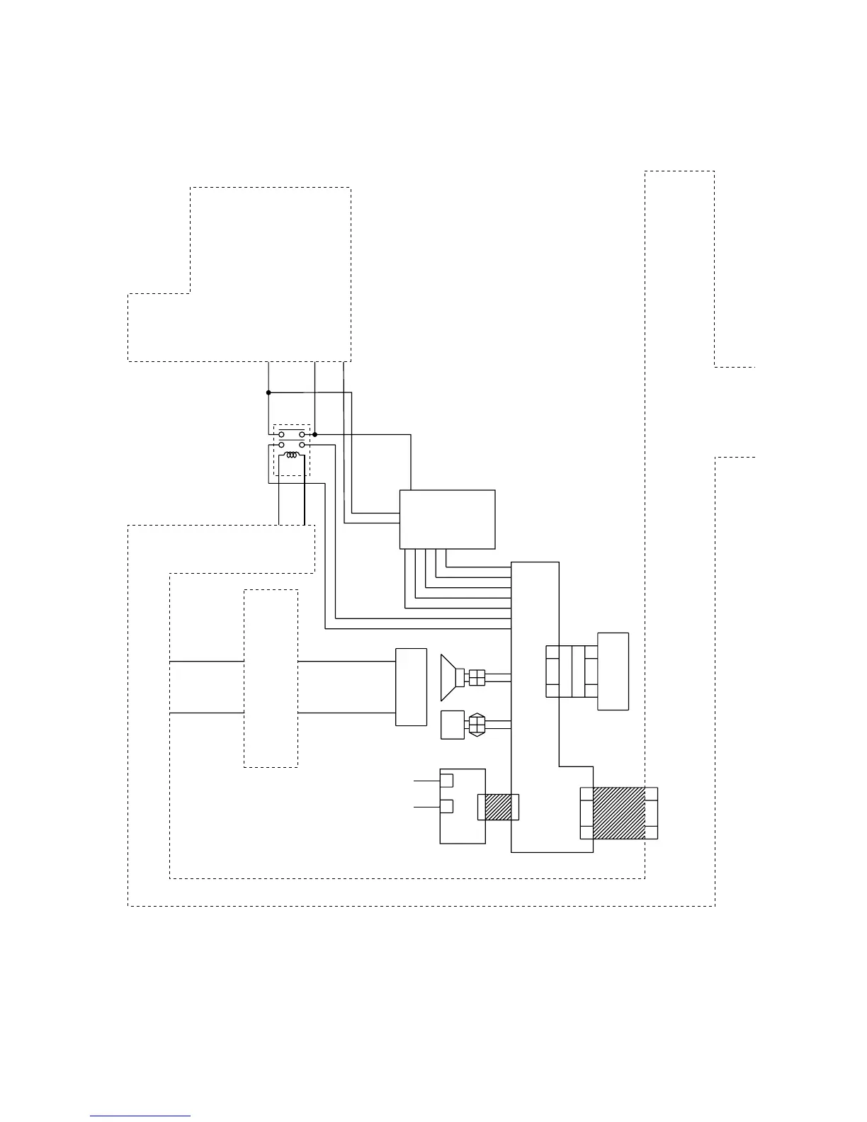
Figure 1-1-3
The fax system consists of the fax control PCB (FCPCB), NCU PCB (NCUPCB), auxiliary power source PCB (APSPCB),
fax operation unit PCB (FOPCB), speaker (SP), backup battery (BUBAT) and optional add-on memory.
 Loading...