3B1
2-1-1
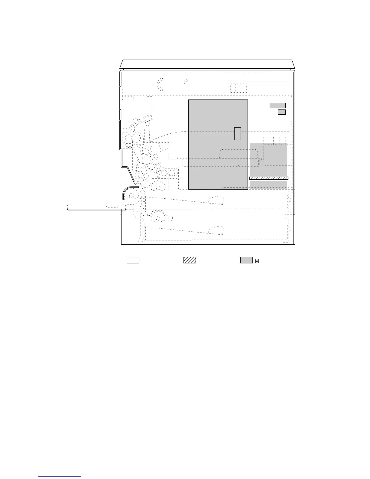
2-1-1 Electrical parts layout
Figure 2-1-1
1. Fax control PCB (FCPCB) ........................... Modulates, demodulates, compresses, decompresses and smoothes out
image data, and converts resolution of image data.
• Add-on memory* ........................................ Expands memory capacity for image data and bitmap conversion.
2.NCU PCB (NCUPCB) ................................... Controls connection to the telephone line.
3.Fax operation unit PCB (FOPCB) ................. Consists of fax operation keys and display LEDs.
4.Auxiliary power source PCB (APSPCB) ....... Converts an AC input to generate 5.2 V DC and 12 V DC.
5.Backup battery (BUBAT) ............................... Saves stored image when a power-down occur.
6.Speaker (SP) ................................................ Outputs buzzer, monitoring and speaker sounds.
* Optional.
1
2
5
6
3
4
Machine front Machine inside
Machine rear


 To Next Page