5FF
2-3-2
(1) Paper deck motor drive circuits
CPU
IC8
–
+
24 V DC
5 V DC
24 V DC
24 V DC
CN7-12
CN7-13
PDM1
5 V DC
8
1
22
4
5
1
2
1
2
2
2
1
1
R52
1
3
C
2
1
2
1
2
E
B
21
IC7.2
C17
R49
R53
R40
21
1
2
D3
2
2
R46 R97
C
E1
C2
1E
Q1
K
A
K
A
1
2
D1
B
B
Q7
3
22
1
1
1
R32
R1
3
1
C2
2
R38
Q3
R14
R20
SGND
PGND
PDMPCB
PGND
PGND
16
R3
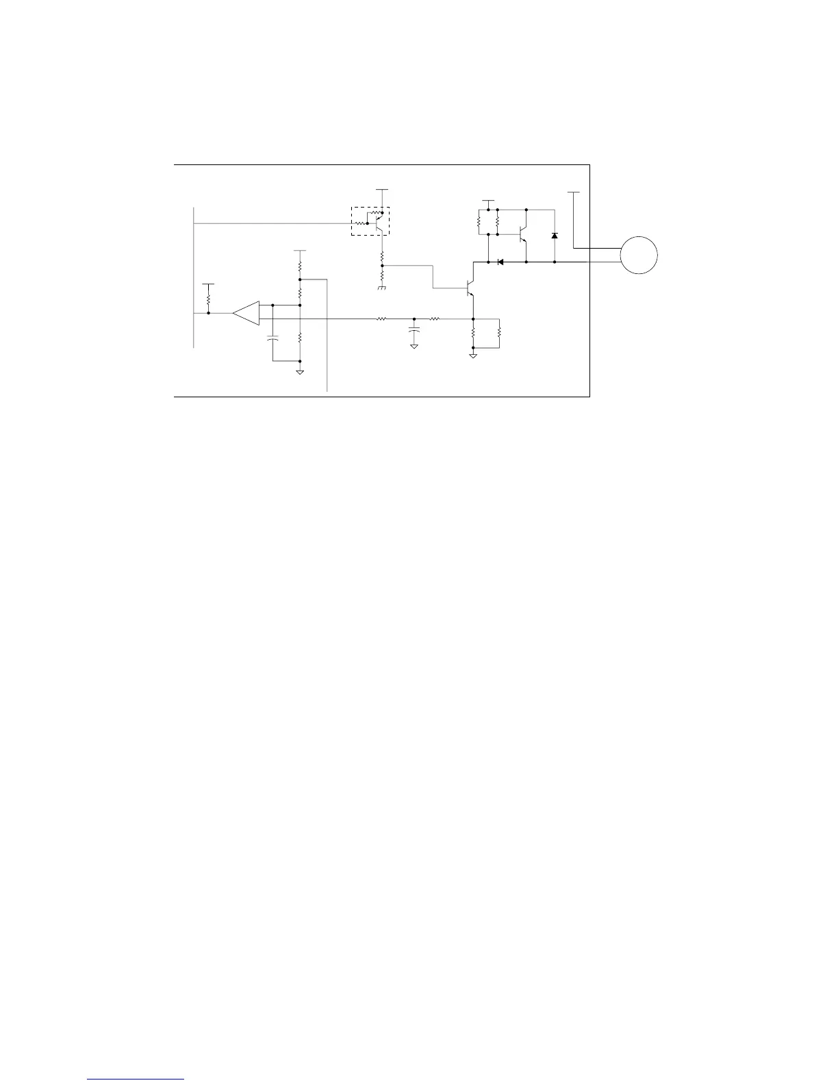
Figure 2-3-2 Paper deck motor 1 drive circuit
The following is a description of the paper deck motor 1 drive circuit. Paper deck motors 1 and 2 are identical.
When pin 8 of the CPU IC8 goes low, transistor Q1 is turned on causing paper deck motor 1 (PDM1) to rotate. When
transistor Q1 is turned off, paper deck motor 1 (PDM1) stops. A brake circuit ensures the prompt stopping of the motor as
follows.
When transistor Q1 turns off, transistor Q7 turns on, supplying 24 V DC to CN7-13 thereby preventing paper deck motor 1
(PDM1) from rotating further under momentum.
To prevent the cassette lift from being raised past its limit, an overcurrent lock detection circuit checks for the overcurrent
that would occur when paper deck motor 1 (PDM1) locks. The current from paper deck motor 1 (PDM1) into transistor Q1
is converted to a voltage by resistor R46. This voltage is input to pin 5 of comparator IC7.2. If this voltage is higher than the
reference at pin 4, 5 V DC is input to pin 16 of CPU IC8. If it is lower, 0 V is input to pin 16. Overcurrent of paper deck motor
1 (PDM1) causes the voltage at pin 5 of IC7.2 to become higher than that at pin 4. This generates 5 V DC at pin 16 of CPU
IC8, which detects overcurrent. If overcurrent lasts more than 1 s, paper deck motor 1 (PDM1) failure is determined, and pin
8 of CPU IC8 outputs 5 V DC, turning paper deck motor 1 (PDM1) off.


 To Next Page