Copyright © 2021 CoreTigo Ltd.
TigoMaster 2TH – PROFINET User Manual
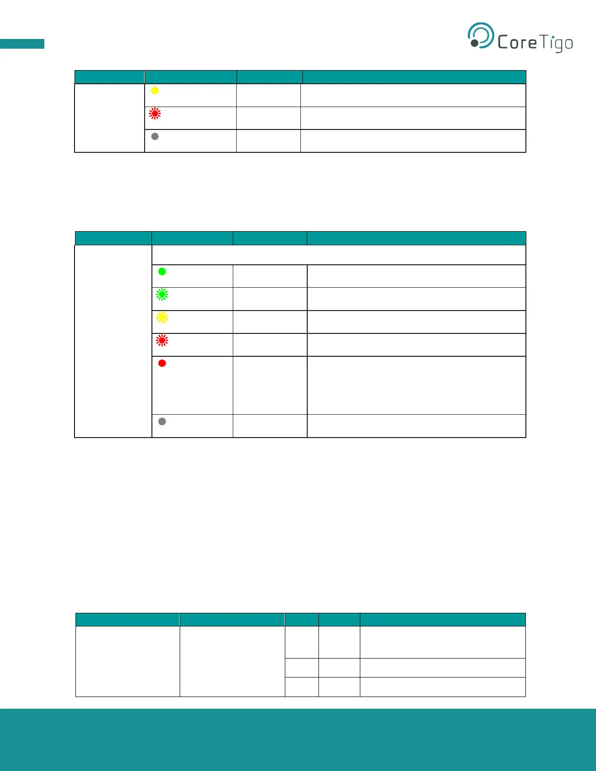
3.2.5.7. Wireless Port Status LEDs
The wireless port status LEDs WP01 … WP16 indicate the states for the wireless ports 1 … 16 as
described in the table below.
Table 14: Wireless track status WP01 … WP16
Duo LED red/green/yellow (yellow = red and green simultaneously)
Pairing success, communication ready
Port errors: Pairing timeout, pairing wrong slot-
type, revision fault, compatibility fault, serial
number fault, process data fault, or cycle time
fault.
3.2.6. Connectors and Interfaces
3.2.6.1. Power Supply
The device’s power is supplied via a connector named X21 (PWR IN). Once connected, users can
connect two supply lines to the connector which are both electrically isolated:
• Supply Line 1: 1L (U1L) and the reference potential 1M
• Supply Line 2: 2L (U2L) and the reference potential 2M
Each pin of connector X21 (PWR IN) is connected to the same pin of socket X22 (PWR OUT) and is used
to forward the power supply to the next device.
Table 15: Power Supply Connectors
+24 V DC power supply for system
and sensor, U
1L
Reference potential for 2L.
Reference potential for 1L.