Copyright © 2021 CoreTigo Ltd.
TigoMaster 2TH – PROFINET User Manual
M12, L-coded, male
5-pin (4 + FE) (X21)
M12, L-coded, female
5-pin (4 + FE) (X22)
+24 V DC power supply for
auxiliary/switched power supply,
U
2L
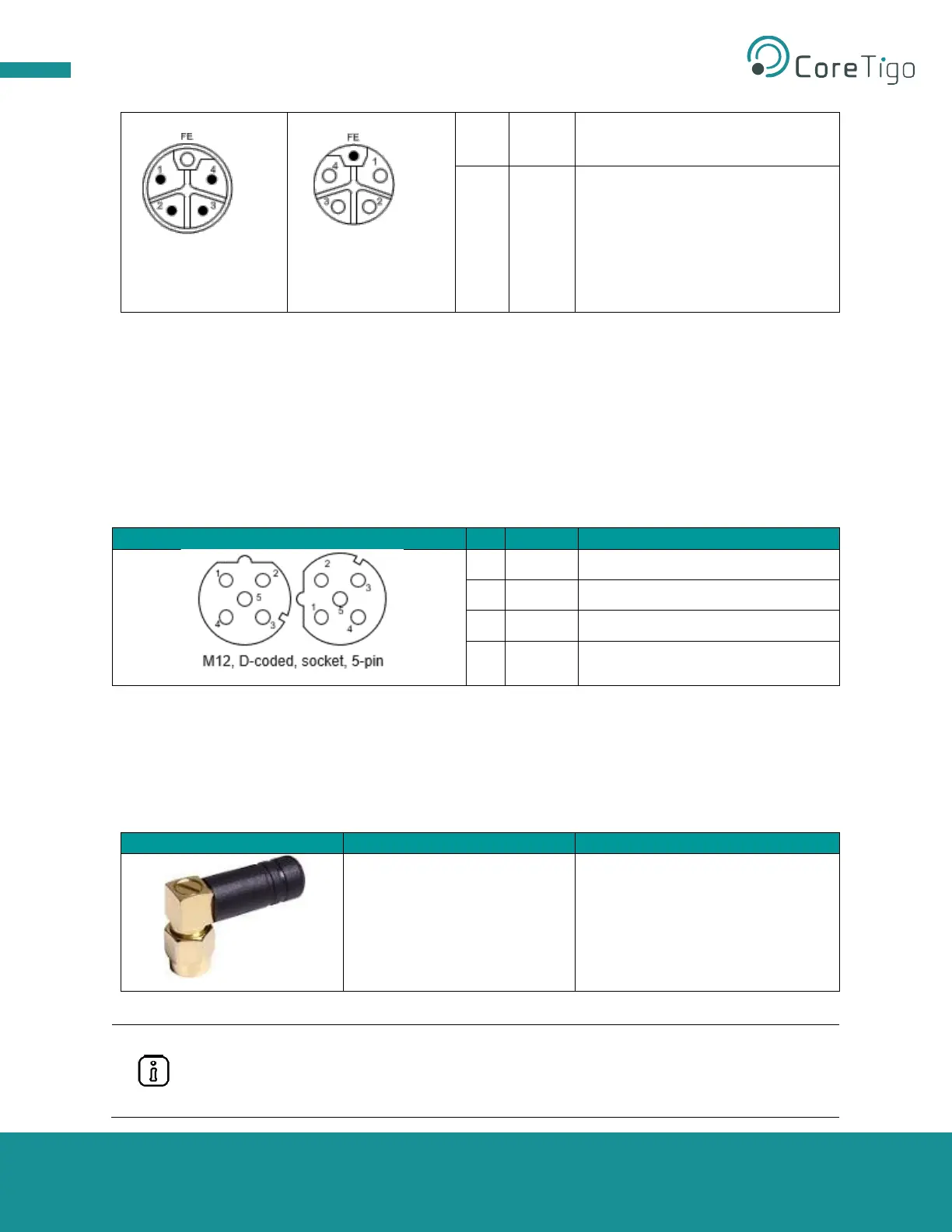
3.2.6.2. Ethernet
Users must use the following connectors to establish a connection with Ethernet interface ports of the
TigoMaster 2TH (PROFINET) device:
• Connector X31 for Ethernet interface port 1 (CH0)
• Connector X32 for Ethernet interface port 2 (CH1)
For identifying the connectors see Figure 1. Connector X31 is item (32), and connector X32 is item (10).
Table 16: Ethernet Connectors
3.2.6.3. SMA Antenna
The TigoMaster 2TH device is equipped with two SMA antenna tracks. Each track supports up to 8, and
both tracks together support up to 16, IO-Link Wireless devices. The types of data transferred (e.g.,
length and data type) may vary depending on the connected IO-Link devices.
Table 17: SMA Antenna
2.4GHz Antenna - 2.4GHz,
5GHz
• Bandwidth: 1000 MHz
• Impedance: 50 Ohms
• Power Rating: 1 W
Tianlu Communication
TLW2.5A-SMA-Male
It is not permitted to use an alternative SMA antenna from the one supplied by CoreTigo
Ltd. Using an alternative SMA antenna may result in a loss of device approval.
Additionally, all three SMA antennas (X1, X2, and X3) must be mounted for proper device
functioning