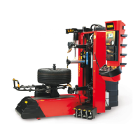
130 Artiglio Master Code User Manual
PNEUMATIC DIAGRAM
1 Female quick connector
2 Filter regulator unit
3 Pressure gauge
A - PEDAL UNIT
4 Pressure switch
5 Inflation limit device
6 3/2 NC Valve Pedal
7 Inflation pressure gauge
8 Manual deflation valve
INFLATRON (OPTIONAL)
9 Selector valve
10 3/2 NC solenoid valve
11 2/2 NC solenoid valve
12 Pressure switch
13 SOLENOID VALVE UNIT
13.1 VC6 5/3 solenoid valve for lifter rotation cylinder command
13.2 VC6 5/3 solenoid valve for lifter vertical movement cylinder command
13.3 VC6 5/3 solenoid valve for head horizontal movement cylinder command
13.4 VD6 3/2 NC + 3/2 NO solenoid valve for bead and bead search and demounting
command
13.5 VF6 3/2 NO + 3/2 NO solenoid valve for bead breaker penetration command
13.6 VB6 5/2 solenoid valve for tool head rotation cylinder command
13.7 VB6 5/2 solenoid valve for triangulation sensor movement cylinder command
13.8 VC8 5/3 solenoid valve for upper bead breaker cylinder command
13.9 VC8 5/3 solenoid valve for lower bead breaker cylinder command
B – LIFTER
14 Cylinder rotation
15 Cylinder vertical movement
C/D – TOOL HEAD UNIT
16 Cylinder head horizontal movement
17 One-way flow regulating valve
18 Quick discharge valve
19 Cylinder movement bead search and demounting
E – BEAD BREAKER PENETRATION
20 Quick discharge valve
21 Cylinder upper bead breaker penetration
22 Quick discharge valve
23 Cylinder low bead breaker penetration