4 Web-based Switch Configuration D-Link Smart Managed Switch User Manual
64
MSTI ID: Enter the MSTI ID in this field. An entry of 0 denotes the CIST (default MSTI).
Priority: Enter the new priority in the Priority field. The user may set a priority value between 0-61440.
Click the Apply button to implement changes made.
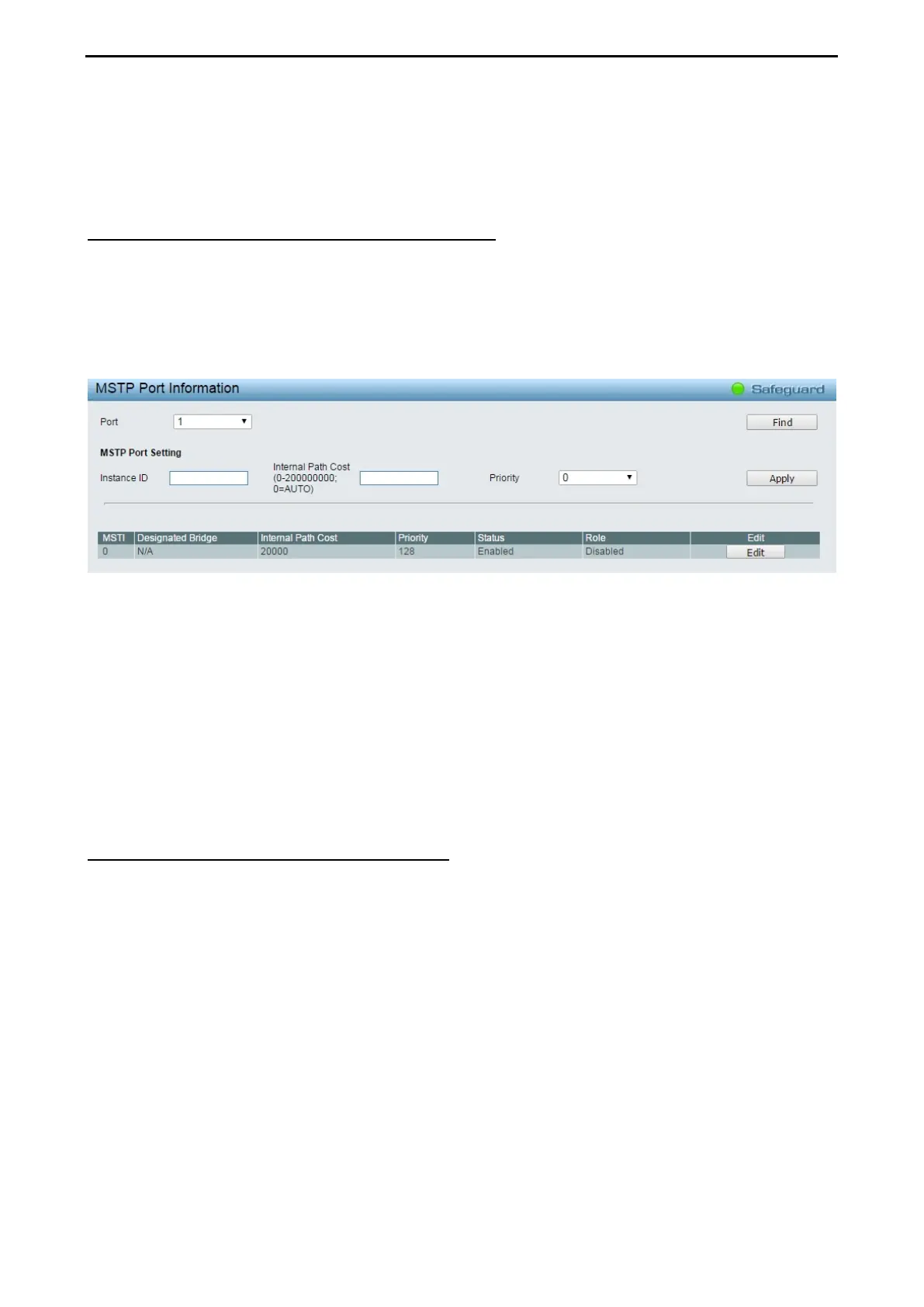
L2 Functions > Spanning Tree > MSTP Port Information
The MSTP Port Information page can be used to update the port configuration for an MSTI ID. If a loop
occurs, the MSTP function will use the port priority to select an interface to put into the forwarding state. Set
a higher priority value for interfaces to be selected for forwarding first. In instances where the priority value is
identical, the MSTP function will implement the lowest MAC address into the forwarding state and other
interfaces will be blocked.
To View the MSTI settings for a particular port, select the Port number and click Find button. To modify the
settings for a particular MSTI Instance, click Edit button, then modify the MSTP Port Setting and click Apply.
Figure 4.69 – L2 Functions > Spanning Tree > MST Port Information
Instance ID: Displays the MSTI ID of the instance being configured. An entry of 0 in this field denotes the
CIST (default MSTI).
Internal Path Cost (0=Auto): This parameter is set to represent the relative cost of forwarding packets to
specified ports when an interface is selected within a STP instance. The default setting is 0 (auto).
0 (Auto) - Selecting this parameter for the internal Cost will set quickest route automatically and
optimally for an interface. The default value is derived from the media speed of the interface.
Value 0-2000000 - Selecting this parameter with a value in the range of 0 to 2000000 will set the
quickest route then a loop occurs. A lower internal cost represents a quicker transmission.
Priority: Enter a value between 0 and 240 to set the priority for the port interface. A higher priority will
designate the interface to forward packets first. A lower number denotes a higher priority.
L2 Functions > Link Aggregation > Port Trunking
Physical interfaces can be logical bound by Port Trunking function that helps to increase bandwidth in
efficiency costs. Up to eight Trunk groups may be created, and each group consists up to eight ports. Select
the ports to be grouped together, and then click Apply to activate the selected Trunking groups. Two types
of link aggregation mechanism supported:
Static - Static link aggregation.
LACP - LACP (Link Aggregation Control Protocol) is enabled on the device. LACP allows for the
automatic detection of links in a Port Trunking Group.
Disable - Remove all members in this trunk group.
 Loading...