1 Product Introduction D-Link Smart Managed Switch User Manual
5
5
CAUTION: The equipment power supply cord shall be connected
to a socket-outlet with earthing connection.
Le cordon d'alimentation de l'équipement doit être
branché sur une prise de courant dotée d'une connexion à la terre.
CAUTION: The equipment is designed for building installation and
not intended to be connected to exposed (outside plant) networks
including campus environment and the ITE is to be connected only
to PoE networks without routing to the outside plant." or
equivalent.
ATTENTION: L’équipement est conçu pour une installation dans
un bâtiment et ne doit pas être connecté à des réseaux exposés
(installations extérieures), notamment des environnements de
campus, et l’ITE doit être connecté uniquement à des réseaux PoE
sans acheminement vers une ins
tallation extérieure." ou
équivalent.
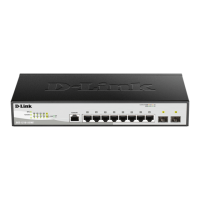
NOTE: The port 1 ~ port 8 are PoE ports. When user press the
Mode button to PoE mode, only port 1 ~ port 8 will light up.
NOTE: Once user enter in loader mode, please
(standalone version 2.0.2.4 on
DNA3.x.x.x)) to download the image for recovery, or call D-Link
Technical Support for further assistance.
Rear Panel
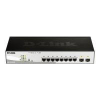
Figure 1.4 – DGS-1210-10P Rear Panel
Power: Connect the supplied DC external power 54V/1.574A cable to this port.
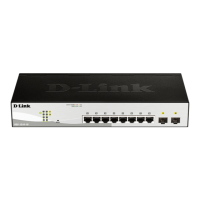
DGS-1210-10MP
8-Port 10/100/1000Mbps plus 2 SFP Ports (100/1000Mbps) Smart Managed PoE Switch.
Front Panel
 Loading...