1 Product Introduction D-Link Smart Managed Switch User Manual
16
ATTENTION: Le cordon d'alimentation de l'équipement doit être
branché sur une prise de courant dotée d'une connexion à la terre.
CAUTION: The equipment is designed for building installation and
not intended to be connected to exposed (outside plant) networks
including campus environment and the ITE is to be connected only
to PoE networks without routing to the outside plant." or
equivalent.
ATTENTION: L’équipement est conçu pour une installation dans
un bâtiment et ne doit pas être connecté à des réseaux exposés
(installations extérieures), notamment des environnements de
campus, et l’ITE doit être connecté uniquement à des réseaux PoE
sans acheminement vers une installation extérieure." ou
équivalent.
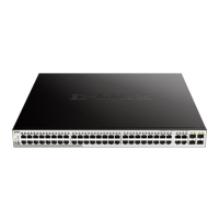
NOTE: The port 1 ~ port 48 are PoE ports. When user press the
Mode button to PoE mode, only port 1 ~ port 48 will light up.
NOTE: Once user enter in loader mode, please
use DNA tool
(standalone version 2.0.2.4 only (No support by Chrome
DNA3.x.x.x)) to download the image for recovery, or call D-Link
Technical Support for further assistance.
Rear Panel
Figure 1.20 – DGS-1210-52MP Rear Panel
Power: Connect the supplied AC power cable to this port.
LED Indicators
The Switch supports LED indicators for Power, Fan, and Link/Act for each port. The following shows the LED
indicators for the DGS-1210 series Smart Managed Switch along with an explanation of each indicator.
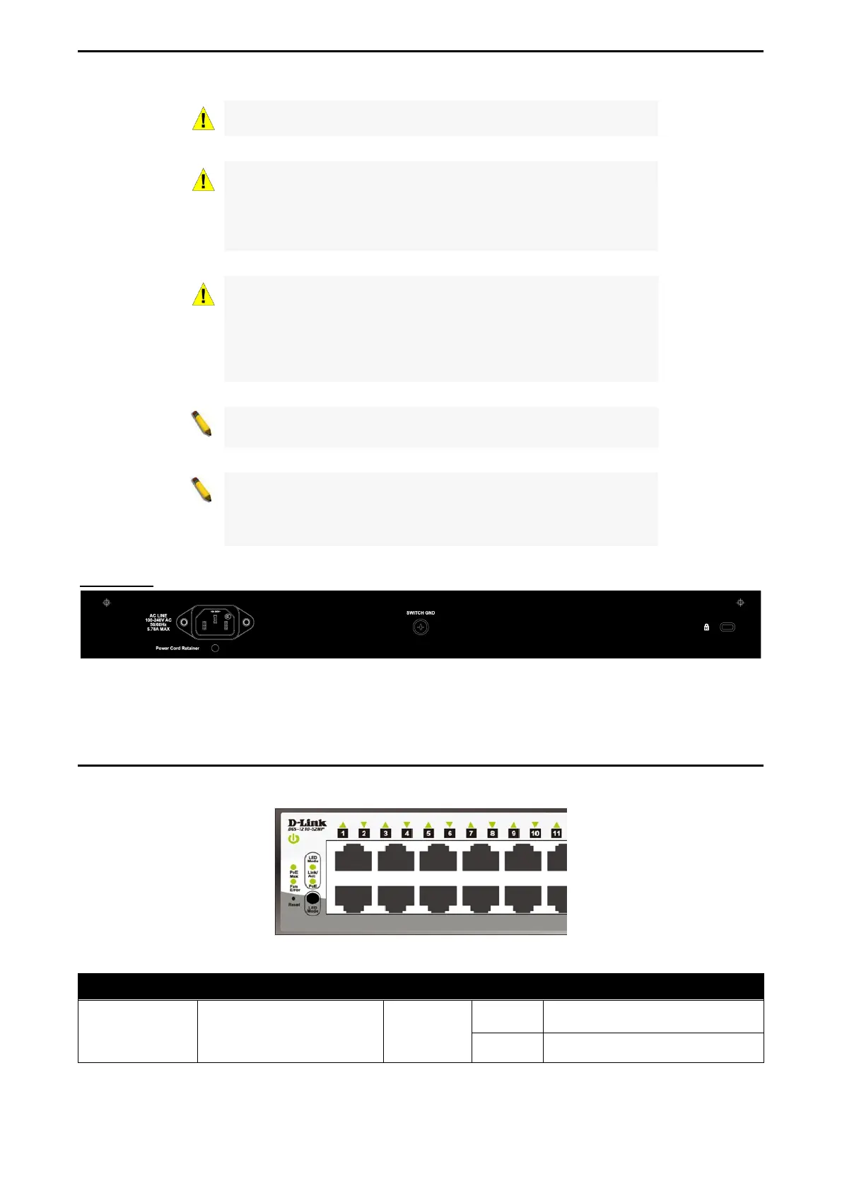
Figure 1.21 –LED Indicators on DGS-1210 series
Location LED Indicative Color Status Description
Per Device Power Green
Solid Light
Power on.
Light off Power off.
 Loading...