ENGLISH
GB
28
Further information and details on the MODBUS and LON bus interface
are available at the following link:
http://www.dabpumps.com/evoplus
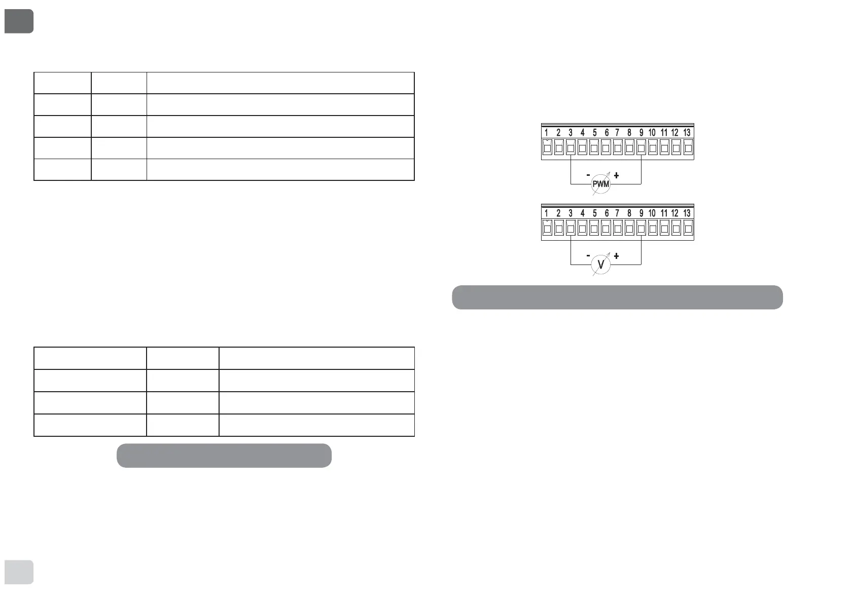
8.2.3 Analogue Input and PWM
Figure 8 shows the wiring diagram of the external signals 0-10V and
3:0$VPD\EHVHHQIURPWKH¿JXUHWKHVLJQDOVVKDUHWKHVDPHWHU-
minals on the terminal board, so they are mutually exclusive. If you want
to use an analogue control signal, you will have to set the type of signal
from the menu (see par. 12 Page 7.0).
Further information and details on the MODBUS and LON bus interface
are available for download at the following link:
http://www.dabpumps.com/evoplus
If the EXT and Economy functions have been activated from the control
panel, the system will behave as follows:
IN1 IN2 System Status
Open Open Pump stopped
Open Closed Pump stopped
Closed Open Pump running with set-point set by the user
Closed Closed Pump running with reduced set-point
8.2.2 MODBUS and LON Bus
EVOPLUS circulators provide serial communication through an input
567KHFRPPXQLFDWLRQLVUHDOLVHGDFFRUGLQJWR02'%86VSHFL¿-
cations.
With MODBUS it is possible to set the circulator operating parameters in
remote mode such as, for example, the desired differential pressure, the
LQÀXHQFHRIWHPSHUDWXUHWKHUHJXODWLQJPRGHHWF$WWKHVDPHWLPHWKH
circulator can provide important information on the system status.
For the electrical connections refer to Figure 6 and to Table 4:
MODBUS Terminals Terminal no. Description
A 2 Terminal not inverted (+)
B 1 Terminal inverted (-)
Y3 GND
7KH02'%86FRPPXQLFDWLRQFRQ¿JXUDWLRQSDUDPHWHUVDUHDYDLODEOHLQ
the advanced menu see Par.12).
EVOPLUS circulators also have the possibility of communicating on LON
bus through external interface devices.
Table 4: RS_485 MODBUS terminals
Figure 8: Pull-out 13-pole terminal board: 0-10V inputs and PWM
 Loading...